Table of Contents
- See Also
- opals::IFillGaps
Aim of module
Detects gaps (i.e. void pixels) in raster models and provides several interpolation methods to close them.
General description
The generation of Digital Terrain Models (DTM) usually leads to void pixels where buildings and vegetation were removed. Module FillGaps aims to close these gaps with qualified approximation of void pixel using information of valid neighbouring pixels. In a first step, connected void pixels get joined to gap objects with boundary information. Each of the boundary pixels is adjacent to at least one void pixel and contains a valid pixel value. Based on the boundary information the void pixels will be filled with qualified values in a second step.
The following fill methods (parameter method) can be used to close gaps:
- adaptive - gaps will be filled with a moving plane interpolation with Inverse Distance Weighting (IDW)
- kriging - gaps will be filled with kriging interpolation based on the boundary pixels
- max - take the maximum value of the boundary pixels as a fill value for all void pixels
- min - take the minimum value of the boundary pixels as a fill value for all void pixels
- plane - gaps will be filled with a tilted fitting plane approximation for all boundary pixels
- triangulation - gaps will be filled with interpolated values from triangulation of the boundary pixels
By default, the entire raster data set is filled. To fill only a part of the data set (e.g. along a flight strip), the fill area can be defined with the parameter fillMask as Shape-File (*.shp) or raster mask (e.g. *.tif). A good option is to use the module Module Bounds to determine the convex hull or the alpha shape of your dataset.
Boundary ratio
To detect outer boundaries of the dataset and avoid filling them with inappropriate values the parameter boundaryRatio is used. The boundaryRatio defines the minimum ratio of valid boundary pixels of a gap to the total number of boundary pixels, including the pixel at the edge of the picture.

The boundary ratio describes how well a gap is described by bordering pixels. If a gap has, for example, 15 valid boundary pixel with 20 boundary pixel in total, the boundary ratio is 0.75, which means that the gap is 75% bounded. Only gaps with a boundary ratio greater than or equal to the given threshold boundaryRatio will be processed and filled.
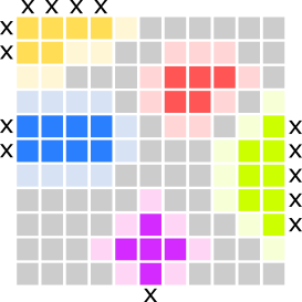
Examples for boundary ratio (see figure below):
- yellow - 5 valid boundary pixels, 11 total - boundary ratio = 0.455
- red - 9 valid boundary pixels, 9 total - boundary ratio = 1.0
- green - 7 valid boundary pixels, 12 total - boundary ratio = 0.58
- pink - 7 valid boundary pixels, 8 total - boundary ratio = 0.875
- blue - 10 valid boundary pixels, 12 total - boundary ratio = 0.83
Adaptive plane with Inverse Distance Weighting (IDW)
If method adaptive is chosen to fill the gaps, an adaptive plane is fitted for each void pixel. The plane fit is performed based on all valid boundary pixels of a gap, with an adaptive weighting (parameter adaptive.weightFunc) of the pixels based on the distance to the void pixel, where the plane is calculated. The default weighting function  is used for the inverse distance weighting (IDW4) of boundary pixels. This means that a boundary pixel which is relatively far away from the void pixel gets a weight close to zero, while a close-by boundary pixel gets a weight close to one. By using this method, two neighbouring void pixels have similar weights on the boundary pixels in the plane-fit, thus, the method always results in a smooth interpolation within the gap.
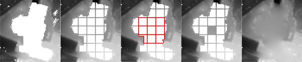
Note: Due to the adjustment of weights in the plane fit computation for each pixel, considerable performance losses are to be expected for large gaps. To overcome this issue a subdividing strategy has been implemented, where the gap is divided into a grid with cell size adaptive.gridSize (see Figure below). In a first stage of the subdivided fill method only the grid outlines are computed with adaptive weighting based on all gap boundary pixels. In the second step all cells of the subdivided gap are filled by using the grid pixels of a 3x3 cell neighbourhood, which have been computed in the previous step. The parameter adaptive.maxPixelRigorous can be used to specify the maximum pixel size of a gap to be filled with the rigorous adaptive fill using all valid boundary pixels.
Parameter description
Remarks: estimable
Path to the output raster image file in GDAL supported format
Estimation rule: The current directory and the name (body) of the input file are used as file name basis. Additionally, the postfix '_filled' plus the output format specific extension is added.
Remarks: estimable
Use GDAL driver names like GTiff, AAIGrid, USGSDEM, SCOP... .
Estimation rule: The output format is estimated based on the extension of the output file (*.tif->GTiff, *.dem->USGSDEM, *.dtm->SCOP...).
Remarks: mandatory
Possible values:
  min ............. Fill gap with minimum value of boundary points
  max ............. Fill gap with maximum value of boundary points
  plane ........... Uses tilted plane fit to fill gaps
  adaptive ........ Uses adaptive plane fit with inverse distance weighting
  triangulation ... Uses triangulation of boundary points
  kriging ......... Fill gap with kriging interpolation
The different fill methods use the boundary points of a gap for the approximation of void pixels inside the gap.
Remarks: default=IDW:4
The following predefined formulae can be used:
IDW1.... inverse linear distance (1/d)
IDW2.... inverse squared distance (1/(d^2))
IDW:i... inverse distance to the power of i (1/(d^i))
where 'd' denotes the 2D distance between the current void pixel and a valid boundary pixel of a gap
Remarks: default=10000
This value is only used for the adaptive fill method and specifies the maximum area of a gap to be filled rigorous,using the entire gap boundary for the computation of the pixel values. Larger gaps are processed in subdivided grid structure for a performance improvement.
Remarks: default=50
This value specifies the grid size for subdividing large gaps in the filling process if the area is larger than maxAreaRigorous.
Remarks: default=0.6
Ratio between the number of valid boundary pixel and the total number of boundary pixel of a gap including pixel that lie along the edge of the image or specified bounds. Gaps with a boundary ratio lower than the specified minimum boundary ratio will not be filled.
Remarks: optional
This parameter can be either a vector file (supported by opalsImport, e.g. *.shp) containing a polygon which specifies a boundary for the area where the gaps should be filled, or a GDAL raster mask (e.g. *.tif) with a grid structure identical to the input raster, where pixels with the value '1' are to be filled. Use opalsBounds or GIS tools to create the vector or raster mask for the fill area. By default - if no fillMask is given - the entire raster data set is filled.
Remarks: default=-1
This value specifies the maximum area of a gap to be filled (in units^2). If the parameter is omitted or set as -1, gaps of any size will be filled (if they are within the bounds).
Remarks: optional
Possible values:
  BoundaryMask ..... Write file with boundary pixels of individual gaps
  BoundaryValues ... Write file with boundary pixels showing their actual value
  MBR .............. Write minimum bounding rectangles of individual gaps
  VoidMask ......... Write file with void pixels of individual gaps
Write additional gap information to files. The outFile parameter is used as file name basis. Additionally, a postfix is added to the filename, based on the selected gap information (e.g. _boundary, _void, boundary_values, _mbr).
Examples
The data used in the following examples can be found in the $OPALS_ROOT/demo/ directory. As a prerequisite the data of (flyover.laz) are imported into an OPALS data manager and a raster DTM is calculated using the following commands:
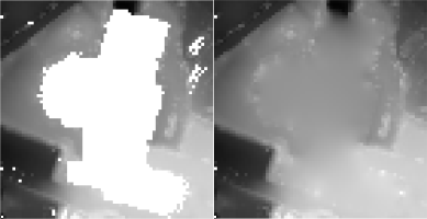
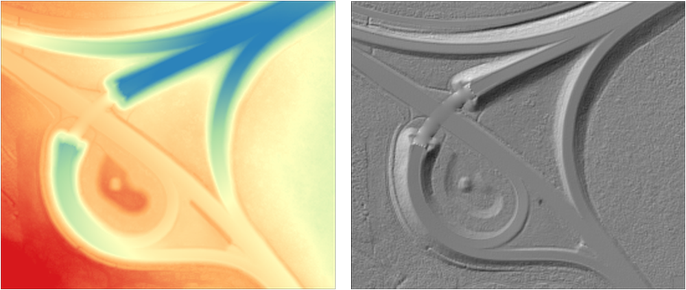
The dataset contains a flyover over a highway, which needs to be filled with proper values.
Example 1:
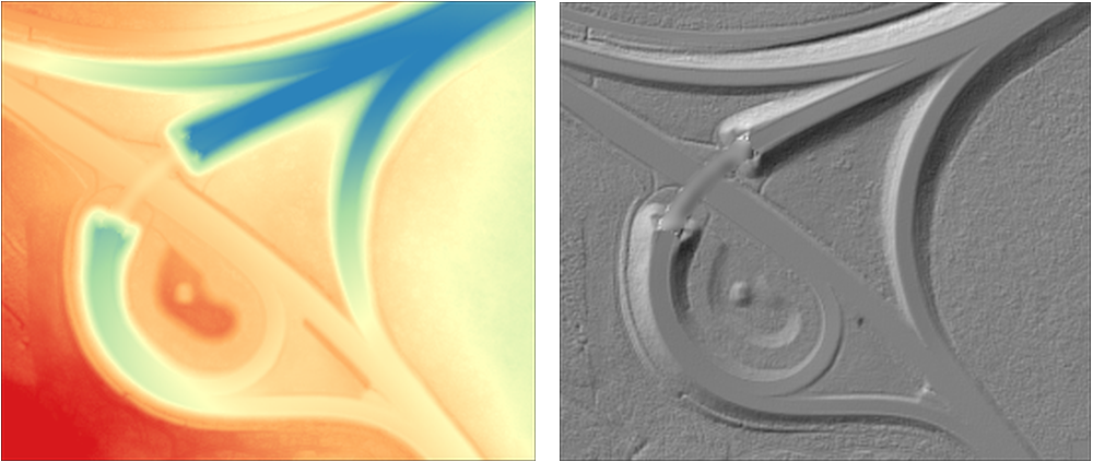
Example 2:

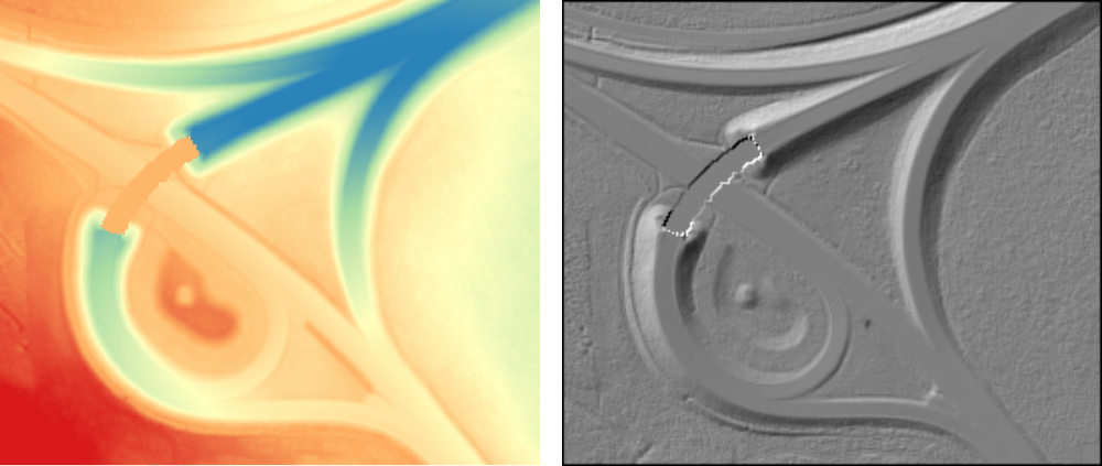
Example 3:
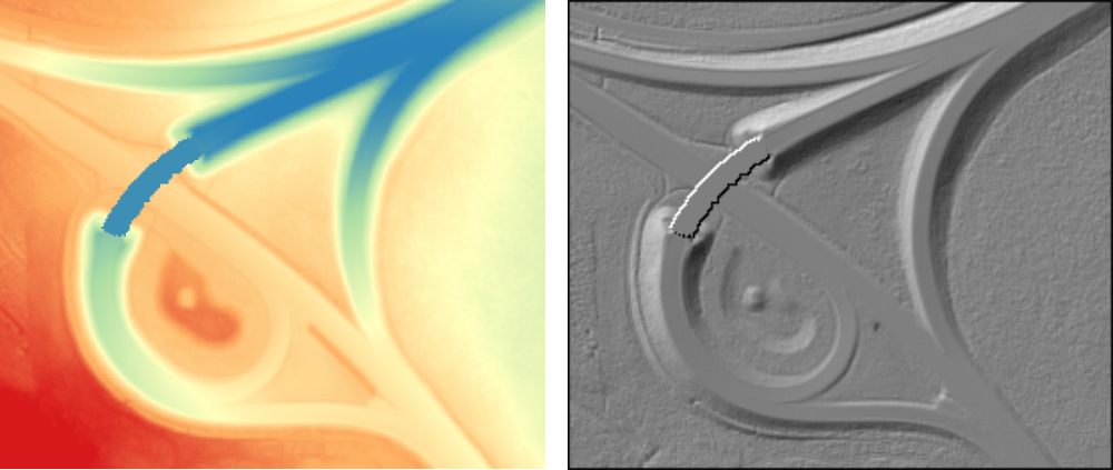
Example 4:

Example 5:
Example 6:
- Date
- 05.01.2017