Table of Contents
- See Also
- opals::ITranslate
Aim of module
Performs format conversion for vector data files with additional read support of GDAL rasters.
General description
Module Translate is a tool providing data format conversion functionality. Up to now, it supports the reading/writing of vector data formats (LAS, ESRI Shapefile, ODM, ASCII /binary, etc.). In the longer perspective Module Translate will also support raster file conversion and coordinate system transformations.
The main parameters are a single or multiple input file names (inFile) and the output file name (outFile). The respective data format is automatically estimated based on the file contents (input) and/or extension (output) but can also be defined explicitly (iFormat, oFormat). In both cases, well defined standard formats as described in Supported data formats as well as arbitrary ascii or binary data formats based on OPALS Format Definition XML files are supported. In case that no output format is specified, the output file is created using the file format and structure of the input file. This is especially useful if only a subset of the data should be written to the output by specifying a filter. For details on filters and how they are defined please refer to the Filter manual. Please note that, in contrast to Module Import only a single input format is supported. Thus, if multiple input files are specified, all files must share the same data format.
An additional functionality of Module Translate is the application of a 3D affine transformation (trafo) in the course of file format conversion. The transformation parameters are typically computed by other OPALS modules like Module LSM, Module ICP or Module GeorefApprox.
Splitting file content
Furthermore, Module Translate supports splitting of the input file contents into separate output files based on a specific attribute of the dataset splitbyAttribute. This feature is, e.g., useful to extract the original flight strips from tiled datasets via a strip identifier (e.g. PointSourceId, cf. Example 5:) or to divide a multi-return dataset into 1st, 2nd, ..., nth echo data files (EchoNumber, cf. Example 4:). While the feature is supported for all numeric types, integer-valued attributes constitute the standard usage case. For each distinct attribute value, a separate file is created. Please note that real-valued attributes (float, double) are automatically casted to integer.
Coordinate Reference System transformation
As a general rule within OPALS, data are expected in the same Coordinate Reference System (CRS) whenever multiple file inputs are supported. This applies to modules accepting file lists (e.g. inFile in Module Import , Module Algebra ...) and modules offering multiple (input) file parameters (e.g. inFile and trjFile in Module Import or inFile and gridFile in Module Snellius ...). Module Translate enables CRS transformations via the parameters inCRS, outCRS, and operation, available within the crsTrafo group. The implementation is based on the respective part of the GDAL/OGR library, which in turn internally uses the PROJ library.
In case the input datasets do not contain CRS information, the input reference system can either be provided via inCRS as a WKT string, a PROJ string, or an EPSG code. The same applies to the output reference system (outCRS), which is the only mandatory parameter for performing coordinate system transformations. Please refer to the CRS page for more information about reference system definition.
Please further note that the global parameter coord_ref_system is considered, if CRS information is neither stored on the data file nor explicitly set via inCRS. In case of multiple definitions, the following precedence is enforced: (i) inCRS, (ii) CRS information stored on the data file, (iii) coord_ref_system.
Starting from version 6.0, the PROJ library supports a flexible framework for constructing user-defined transformation pipelines. Built around this so-called "CoordinateOperation" feature, Module Translate offers a generic way for transforming data between different CRS including datum shift, change of height system, and gidi-shift based correction of inhomogeneous reference systems. The possible transformation paths are depicted in the following Figure 1.
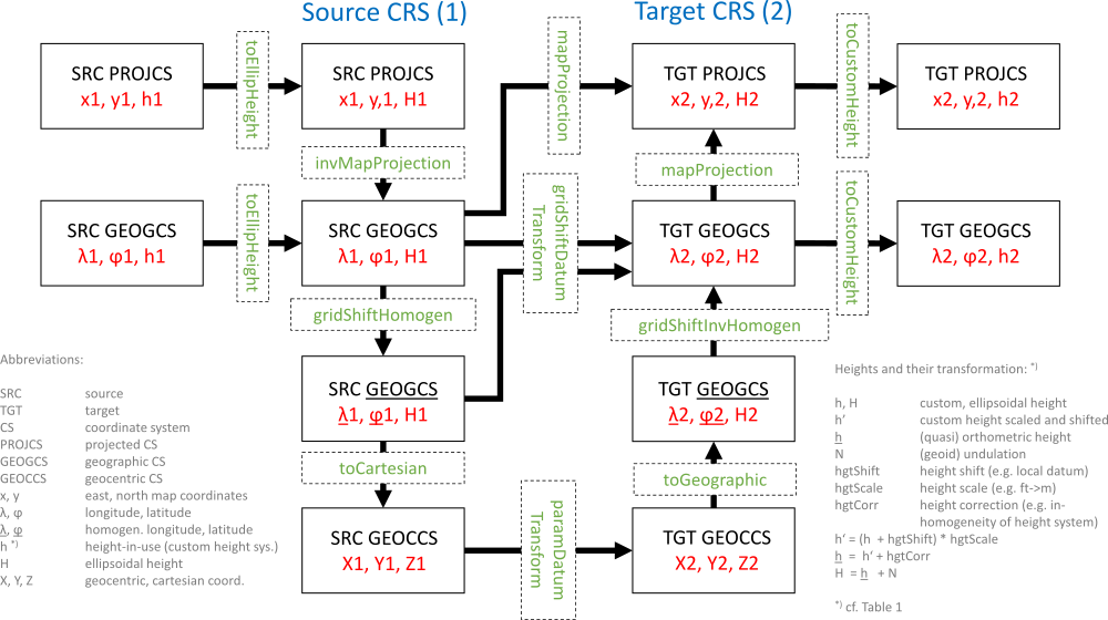
In Figure 1, the dashed and solid boxes denote source and target reference systems including potential intermediate systems, the thick arrows indicate possible transformation routes, and the green dashed boxes finally represent the available atomic coordinate operations between two systems. Some of these operations require further parameters as detailed in the table below. Syntactically, a transformation pipeline (operation) is a list of strings, each containing the textual, function-style description of an individual operation. Each string consits of the name of the operation (i.e. labels of green boxes in Figure 1) followed by 0..N arguments in key=value enclosed in parentheses and multiple arguments are separated by commas.
The individual operations, their specific meaning and required parameters are listed in the table below:
| operation | arguments | dim. | description |
|---|---|---|---|
| toEllipHeight | hgtShift=<float>, hgtCorr=<path> | invHgtCorr=<path>, undulation=<path> | 1D | Converts custom heights h' (e.g. orthometric/normal/dynamic/tidal/etc. heights) to ellipsoidal heights H. The transformation may include a a constant offset (hgtShift) as well as the application of correction grids to account for inhomogenities of the source height system (hgtCorr = -invHgtCorr) and (geoid) undulations (undulation). Cf. Figure 1 for the transformation formulae. The height correction and undulation files are expected in geographic coordinates (lon/lat) of the source system and in <a href="https://vdatum.noaa.gov/docs/gtx_info.html>GTX file format</a). |
| toCustomHeight | undulation=<path>, hgtCorr=<path> | invHgtCorr=<path>, hgtShift=<float> | 1D | Converts ellipsoidal heights H to custom heights h. The same rules as above apply. The height correction and undulation files are expected in geographic coordinates (lon/lat) of the target system. |
| mapProjection | — | 2D | Converts geographic coordinates (lon/lat) to map projection coordinates (x/y or easting/northing, respectively). No arguments required as the necessary parameters are stored with the CRS definitions (WKT, proj, EPSG code) |
| invMapProjection | — | 2D | Converts map projection coordinates (x/y or easting/northing, respectively) to geographic coordinates (lon/lat). No arguments required (as above). |
| toCartesian | — | 3D | Converts 2D-geographic coordinates + 1D-ellipsoidal heigths (lon/lat/H) to 3D Earth-Centered-Earth-Fixed (ECEF) cartesian coordinates (X/Y/Z). No arguments required (as above). |
| toGeographic | — | 3D | Converts ECEF cartesian coordinates (X/Y/Z) to 2D-geographic coordinates + 1D-ellipsoidal heigths (lon/lat/H). No arguments required (as above). |
| paramDatumTransform | float*0 | float*3 | float*7 | float*10, inverse = 0 | 1 | 3D | Converts ECEF cartesian coordinates (X/Y/Z) from one geodetic datum to another using a parametric transformation: 3P: shifts only, 7P: Spatial similarity transformation (Helmert: shifts, rotations, scale), 10P: Molodensky=Spatial similarity transformation with reduction point (3 shifts, 3 rotations, 1 scale, 3 reduction point shifts). The optional inverse key can be used, if the transformation paraemters are known in the opposite transformation direction. In this case, parameter inversion is performed internally. If no parameters are defined (i.e, float*0), the parameters are automatically extracted from the CRS definion strings (e.g.: WGS: TOWGS84). |
| gridShiftDatumTransform | gridShift=<path>, inverse = 0 | 1 | 2D | Converts geographic coordinates (lon/lat) from source datum to target datum via application of (ntV2) grid shift file (gridShift). Please use invGridShift, if the grid shift files denote the opposite transformation direction. |
| gridShiftHomogen | gridShift=<path>, inverse = 0 | 1 | 2D | Performs homogenization of geographic coordinates (lon/lat) via application of (ntV2) grid shift file (gridShift). Please note that no datum transformation is performed in this step but the grid shift values (dLon/dLat) are only intended to correct potential inhomogenities of the source CRS (gridShift=-invGridShift). |
| gridShiftInvHomogen | gridShift=<path>, inverse = 0 | 1 | 2D | Performs inverse homogenization of geographic coordinates (lon/lat) via application of (ntV2) grid shift file (gridShift). Please note that no datum transformation is performed in this step but the grid shift values (dLon/dLat) in the grid shift file are only intended to restore the inhomogenities of the target CRS (gridShift=-invGridShift). |
Please find concrete examples here.
Parameter description
Remarks: estimable
Estimation rule: The current path and the name (body) of the (first) input file is used as file name basis (stem). Depending on the number of input files and whether of not -splitByAttribute is specified, the output file is named as follows:
nr. inFiles==1 and splitByAttribute=no : stem + '.translatedTo' + oFormat extension
nr. inFiles >1 and splitByAttribute=no : stem + '.multipleInputsTranslatedTo' + oFormat extension
splitByAttribute=yes : stem + '_' + name-of-attribute name + '_' + value-of-attribute + oFormat extension
In the latter case, value-of-attribute denotes the unique values of the splitting attribute found in the input datasets.
Remarks: default=auto
Input file format. If no format is specified the file content is used to recognise the file format.
Remarks: optional
Defines the output format. If not specified, the output file written in the very same format as the input file.
Remarks: optional
A filter string in EBNF syntax as described in section 'Filter syntax' can be passed to restrict the input data set (e.g. to consider last echoes only)
Remarks: optional
An eventually passed affine 3-d transformation is applied during data import. The passed value is converted internally into a single filter tree for parameters 'filter' and 'trafo'. If both are to be used, make sure to mark the position where in the filter's string 'trafo' shall be introduced, using curly brackets {}
Remarks: optional
If specified, the output is split into individual files based on the respective attribute. This can, e.g., be used to separate flight strips from tiled data using the PointSourceId attribute or to separate the 1st, 2nd, etc. echoes based on the EchoNumber attribute. Please note that this works only for numerical attributes but not for strings. Furthermore, all numerical attributes are automatically converted (i.e. casted) to integer.
Remarks: optional
In case of coordinate transformation the source CRS may be specified either as OGC Well-Known-Text (WKT) string, as proj4 definition string or as EPSG code. This is not needed if the source system is stored within the input file, but can be overwritten by using this parameter.
Remarks: optional
To apply a coordinate transformation specify the target CRS as OGC Well-Known-Text (WKT) string, as proj4 definition string or as EPSG code. In case the input file doesn't contain CRS information, it has to be provided by the inCRS parameter.
Remarks: optional
This parameter is only relevant if translated to ODM(s) and the automatic tile size estimation should be overruled. Inappropriate tile sizes can lead to memory problems or slow performance in later processing steps. On average, 100,000 to 200,000 points should be stored within one tile (check index statistics after export).
Examples
The data used in the following examples can be found in the $OPALS_ROOT/demo/ directory.
Example 1:
The above command converts the file strip31.laz from compressed LAS file format to the ASCII file strip31.laz.convertedTo.fwf. The attributes Amplitude (i.e. LAS intensity), EchoNumber, and NrOfEchos are preserved as they are contained in the predefined FWF format. Please note that the name of the output file is automatically estimated based on the respective estimation rule.
Example 2:
Providing the proper input format definition XML file LAS_1.2._ew.xml which maps the LAS extry byte attribute PulseWidth to the predefined OPALS Datamanager attribute EchoWidth additionally preserves the echo width information in the ASCII output file.
Example 3:
This command reads the LAS file, analyses the echo attributes via the specified filter, and writes all intermediate echo points to a binary XYZ file.
Example 4:
This example demonstrates the usage of splitByAttribute to extract the 1st, 2nd, ..., nth echo from multiple input files.
As a result, seven files named echo_1.las to echo_7.las are created corresponding to the unique echo numbers of the input datasets. Please note that it is not necessary to know the attribute range beforehand, as the uniqueness is checked for each point and new output files are automatically created if needed.
Example 5:
This example illustrates the usage of splitByAttribute to extract the flight strips from an entire flight block dataset based on the attribute PointSourceId.
Please note that in this example no output file name is specified. Module Translate automatically composes the output file names from the name of the input file (strips_), the attribute name (PointSourceId_) and the unique PointSourceId values (11, 21, 31). The following files are hence exported.
Example 6:
This example illustrates the usage of trafo to do 3D affine transformation on a raster dataset based on the result of alignment from Module LSM.
Module Translate automatically composes the output file name from the name of the input file.
Example 6:
This example shows how to perform a simple CRS transformation.
In this example, only the output CRS is set while the input CRS (ETRS89/UTM33) is automatically determined from the file header of the input dataset (strip11.laz). As no user-defined transformation pipeline is specified, the transformation path is automatically determined based on the given CRS definitions. In particular, the TOWGS84 specification of the output CRS (EPSG:31256, MGI, Gauss-Krueger East) is used for performing the datum transition from ETRS89->MGI via a 7P (spatial similarity transformation). Please notethat, as both system definitions are 2D (PROJCS), the transformations is only performed in 2D and consequently only the x,y, coordinates change but not the elevations.
Example 7:
This example shows how to use custom transformation pipelines (operation) to transform global coordinates in UTM33/ETRS89 coordinate frame to the Austrian national system MGI in Gauss-Krueger projection.
Current restrictions:
Currently only point datasets are supported, when running Module Translate with splitByAttribute and with CRS transformations.
- Date
- 17.05.2018