Module LineTopology
See also
opals::ILineTopology

Aim of module

Provides different line merging and topology correction tools for cleaning line networks derived via automatic edge detection.

General description

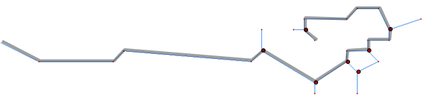
Many application require a continuous and topologically correct line network. Automatic line detection procedures (e.g. based on the Canny algorithm, cf. Module EdgeDetect) result in line networks which need post-processing for fulfilling the above aim of topological consistency and completeness. In the context of topographic mapping structure lines denoting surface slope discontinuities or even height jumps are of crucial importance. They can be regarded as the relevant linear features to portrait the landscape. Whereas full automation is hard to achieve for anthropologically shaped landscapes and manual editing might become necessary to achieve full completeness and correctness Module LineTopology aims at minimizing the manual editing effort by providing multiple line merging and topology correction strategies. Figure 1 shows vectorized line segments resulting from Canny edge detection highlighting the basic problems: (a) gaps in the line course and (b) line nodes/junctions

Fig. 1: Incorrect line network (gap between lines 1 and 2, line nodes/junctions between 2/3 and 3/4

To overcome the above mentioned shortcomings Module LineTopology offers the following strategies (parameter method)

  • merge: Line merging based on best-suited-line-connection analysis. In multiple iterations (maxIter) the locally optimal line connection is searched by evaluating multiple criteria like gap distance, horizontal and vertical line straightness, etc.
  • longest: This processing modes aims at finding the longest continuous line course based on a bi-directional graph (i.e. Dijkstra algorithm). All lines along the shortest path through the graph are connected.
  • clean: The line topology is considered incorrect if any lines intersect between line nodes. Simple and complex intersections at line nodes (V-, T-, and X-junctions) are explicitly tolerated. Inconsistent line networks (in the above sense) are automatically cleaned by opening line violating the topological correctness.

Details: Line merging

Module LineTopology tries to closing small gaps between individual line parts (snapRadius). As the reliability of automatically detected line paths tends to be poorest at the line ending, not only the very endpoints are considered as line connection candidate points but also points at the line end range (revertDist, revertIntervall). For merging two free ending lines the following issues need to be considered:

  • Finding the optimum connection line between two adjacent lines
  • Finding the locally optimum line progression if more the two lines are involved (e.g. Y- or X-shaped junctions)
  • Maintaining topological correctness (Avoiding crossings with other lines of the network when establishing a new line connection).

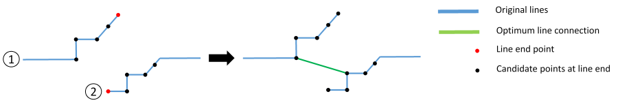
For merging two adjacent line endings the optimum line connection is found by analysing all candidate connections in the end range of both lines. For each connection the following parameters are checked:

  • Length of line connection (smaller gaps are favoured)
  • Horizontal and vertical angular difference between line directions at the candidate points:
  • Straightness of line ending (rectilinear lines are favoured)
  • Distance between line connection candidate point and corresponding line end point (points near the line end are favoured)
  • Lateral distance of imaginary line extensions (to avoid merging of misaligned lines)

Each of the above mentioned parameters is scaled as an individual weight between 0 and 1 and the overall weight of a single connection candidate is obtained by multiplying all individual weights. The user can influence the rating by assigning scale factors for the individual weights (parameter group: weight factor options; dist, angle, revertDist, straightness, perpDist). Figure 2 shows an example where a small angular difference was favoured over a small connection-point-to-line-end-point (i.e. revert) distance.

Fig. 2: Optimum line connection based on point-to-point distance, straightness, angular difference, etc.

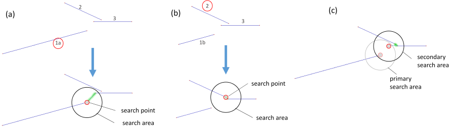
If more than two lines are located within the line connection search area, the optimum line connection pair needs to be determined. As illustrated in Figure 3 a and b different line connections are found depending on the processing sequence. In Module LineTopology the lines are first ordered by descending length. The connecting line found for the longer line 1a in Figure 3a, however, is suboptimal as the connection between line 2 and 3 (Figure 3b) is favourable. Therefore the basic merging strategy outlined above is embedded in a generation based analysis. Starting with line 1b and the found connection candidate (line 3), the candidate selection is extended using line 3. Analysis of the end of line 3 reveals a better connection (to line 2) than was found before for line 1a. In general the described strategy results in globally optimal line connections. However, due to performance considerations the maximum number of search generations can be limited with parameter searchGeneration.

Fig. 3: Determination of optimum line connection pair in complex multi-line environments

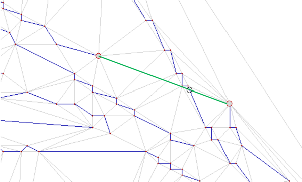
To avoid crossings within the line network introduced by establishing a new line connection, a triangular irregular network (TIN) is constructed from the initial line strings. Each line segment is hereby inserted as a constraint edge in a Delaunay triangulation. By default, a connection candidate is rejected if the connection intersects a contraint edge of the TIN (preventIntersection). Figure 4 shows an example; the green connection line candidate is rejected because it intersects the interjacent line.

Fig. 4: TIN-based analysis of line network intersections when establishing a new line connection

Details: Longest path

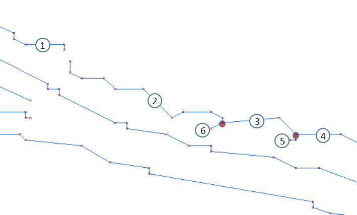
The general idea of processing method longest is to establish those line connections which results in the longest continuous path. First, all lines are ordered by descending length. Starting with the longest line, all line parts sharing a common end point (line intersections) or even exhibiting a small gap are inserted into two directed graphs (one in forward and one in backward direction). Lines are recursively inserted into the graph if the gap distance (snapRadius) and the line progression direction (-opalsparam{maxAngleDev}) are within the acceptable limits. The search for additional connection candidates is then repeated at the end of each inserted line. Original (i.e. input) line strings are hereby inserted as edges and line connections as nodes into the graph. In case of adjacent lines (i.e. end point of 1st line = start point of 2nd line) an additional dot-shaped node is inserted. Finally the Dijkstra algorithm is used to find the shortest path connecting all nodes. For both graphs (forward and backward direction), the nodes featuring the longest path length are chosen and all lines on these specific paths are connected. Subsequently, all original line parts contributing to the described longest path line merge are removed from the line stack and processing is continued with the next longest line (part). The procedure is repeated until the line stack is empty or no more line connection are found. Figure 5 shows a practical example.

Fig. 5: Line merging via longest shortest-path analysis (Dijkstra algorithm)

Details: Topology cleaning

With processing method clean double lines or line segments can be automatically removed. Furthermore, erroneous line intersections are automatically detected and broken open by introducing a small gap (omitDist). Please note, intersections of two lines in a common node are accepted and, thus, the lines are not split up in this case.

Typical workflow

The envisaged application of Module LineTopology is to post-process line vector data stemming from automatic edge detection, in particular with Module EdgeDetect and Module Vectorize. In this specific setup small gaps between otherwise continuous line paths, line crossings, and dangling line segments are likely. Whereas there is no one-for-all strategy yielding optimal results for every case, the following approaches have proven to be successful:

  1. Variant 1:
    • 1st call: Method longest with snapRadius=0 to identify and link the most prominent routes
    • 2nd call: Method merge with snapRadius>0 to find locally optimal line connections
  2. Variant 2:
    • 1st call: Method merge with snapRadius>0 to first establish the locally optimal line connections
    • 2nd call: Method longest with small snapRadius=0 to identify the longest possible continuous routes.

Usage of processing method clean is advisable after manually editing the line vector data to double check and (re)establish topological correctness of the line network.

Parameter description

-inFileinput file
Type: opals::Path
Remarks: mandatory
Path to a raw structure lines file [(B)WINPUT, SHP, ...]
-outFileoutput file
Type: opals::Path
Remarks: mandatory
Path to the output file containing post-processed line info
-methodprocessing method
Type: opals::TopologyProcessingMethod
Remarks: mandatory
Possible values:  
  merge ..... Best candidate merging strategy (iterative)
  longest ... Merge lines based on recursive longest line strategy (Dijkstra)
  clean ..... Build topologically correct line networks
There are three different processing methods
-minLengthminimum line length
Type: double
Remarks: default=10
Specifies the minimum length of a line after concatenation
-maxTolmaximum 3D-pitch for line vertex thinning
Type: double
Remarks: default=0
Line simplification using the Douglas-Peucker algorithm is applied to the input structure line dataset. For each line only those line vertices are preserved which are necessary to ensure that the diviation of the simplified from the original line is smaller than the specified thresh9old. Please note that line simplification is carried out before line topology processing.
-lineVertexDistline vertex spacing interval
Type: double
Remarks: optional
If specified, additional equidistant vertices are inserted between the original line nodes. Please note that the optinal line vertex densification is carried out onbly after line topology processing.
-snapRadiussnap radius
Type: double
Remarks: default=0
Specifies the search radius for line concatenation
-maxAngleDevmaximum bend angles (Hz, V)
Type: opals::Vector<float>
Remarks: default=50 15
Requires two values to specify the maximum bend angle between adjacent line parts in horizontal (value(1)) and vertical (value(2)) direction.
-avgDistaverage distance
Type: double
Remarks: default=5
Specifies the average distance for end segment computation
-debugOutFileoptional debug points file
Type: opals::Path
Remarks: optional
Specifies the file path for an optional output of debug points
-mergeIGroup: Method: Merge
Parameters for best candidate merging strategy
.minWeightminimum weight
Type: double
Remarks: default=0.6
Specifies the minimum weight to accept the best candidate
.relWeightLeadrelative weight lead
Type: double
Remarks: default=0
The relative weight lead specifies a minimum lead of the best candidate to the second best candidate. Only if the lead is higher than the relWeightLead, the candidate can be accepted. If relWeightLead = 0, no check is performed.
.maxItermaximum merging iteration
Type: uint32
Remarks: default=10
Specifies the maximum number of iterations for serching the locally optimal line connection
.revertDistrevert distance
Type: double
Remarks: default=0
Up to which distance from the line end to the inside of the line new optimal connections to other lines can be establised. Possible new end points are computed based on revert interval.
.revertIntervalrevert interval
Type: double
Remarks: default=1
Discretisation interval of computing new possible end points for new optimal connections to other lines. These are computed up to the given revert distance from the line end to the inside of the line.
.searchGenerationsearch generation
Type: uint32
Remarks: default=1
Number of search generations/iterations to find the optimal line connection. Although the line merge process is a local algorithm, finding connection in mutliple generations helps to find the global optimum of all line connection
.preventIntersectionprevent intersection
Type: bool
Remarks: default=1
Prevent interesection of lines by setting this parameter to 'true'
-wfIGroup: weight factor options
weight factor options for best candidate merging strategy
.distweight factor distance
Type: double
Remarks: default=1
.angleweight factor angles (Hz, V)
Type: opals::Vector<float>
Remarks: default=1 1
.revertDistweight factor revert distance
Type: double
Remarks: default=1
.straightnessweight factor straightness
Type: double
Remarks: default=1
.perpDistweight factor perpendicular distance
Type: double
Remarks: default=1
-cleanIGroup: Method: Clean
Parameters for topological line network
.intersectSnapDistomit distance for intersections
Type: double
Remarks: default=0
In case short end line segments emerge after building a clean topological line network (eg. because T-formed line interesection have not been snapped), these end segments will be removed if their length is shorter than given threshold. Setting the parameter to 0 deactivates the end segment omit check.

Examples

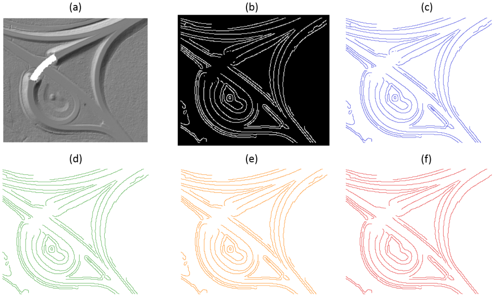
The data used in the following example can be found in the $OPALS_ROOT/demo/ directory. As a prerequisite the data of (flyover.laz) are imported into an OPALS data manager, a DTM grid is calculated, the DTM slope map is calculated and processed with opalsEdgeDetect, and finally the resulting binary raster is vectorized:

opalsImport -inFile flyover.laz -tileSize 100 -coord_ref_sys EPSG:5650
opalsGrid -inFile flyover.odm -outFile flyover_dtm.tif -interpolation movingPlanes -neighbours 8 -searchRadius 2 -selMode quadrant
opalsGridFeature -feature slpDeg -inFile flyover_dtm.tif
opalsEdgeDetect -inFile flyover_dtm_slpDeg.tif -outFile flyover_dtm_canny.tif -sigmaSmooth 1.25 -threshold 1 4
opalsVectorize -inFile flyover_dtm_canny.tif -outFile flyover_dtm_canny.shp

A common routine to get a complete and topologically correct line network is to use the following three steps:

opalsLineTopology -inf flyover_dtm_canny.shp -outf flyover_dtm_canny_step1.shp -cfg linetopology_step1.cfg

The processing in step 1 is done to establish line connections that result in long continuous paths.

opalsLineTopology -inf flyover_dtm_canny_step1.shp -outf flyover_dtm_canny_step2.shp -cfg linetopology_step2.cfg

In the second step the module tries to close small gaps between different lines depending on the specified snapRadius.

opalsLineTopology -inf flyover_dtm_canny_step2.shp -outf flyover_dtm_canny_step3.shp -cfg linetopology_step3.cfg

Step 3 again performs the longest path method to identify the longest possible continuous routes. The input DTM shading, all intermediate and final products of the above example are displayed in Figure 6.

Fig. 6: (a) DTM shaded relief map, (b) Binary edge raster map (Canny algorithm), (c) Raw vectorized edges, (d-f) Cleaned lines after repeat execution of opalsLineTopology (step 1-3)

References

G. Mandlburger, J. Otepka, C. Briese, W. Mücke, G. Summer, N. Pfeifer, S. Baltrusch, C. Dorn, H. Brockmann: Automatische Ableitung von Strukturlinien aus 3D-Punktwolken. in: "Dreiländertagung der SGPF, DGPF und OVG: Lösungen für eine Welt im Wandel", T. Kersten (ed.); Publikationen der Deutschen Gesellschaft für Photogrammetrie, Fernerkundung und Geoinformation e.V., Band 25 (2016), ISSN: 0942-2870; 131 - 142.

Author
gm, jo, mpoechtr
Date
9.2.2017
@ quadrant
quadrant-wise nn selection, ie. nn per quadrant, then 2nd nn per quadrant, ...
opalsVectorize is the executable file of Module Vectorize
Definition: ModuleExecutables.hpp:243
@ movingPlanes
moving (tilted) plane interpolation
@ coord_ref_sys
default coordinate reference system (EPSG Code, WKT string or PRJ-File)
opalsImport is the executable file of Module Import
Definition: ModuleExecutables.hpp:113
opalsEdgeDetect is the executable file of Module EdgeDetect
Definition: ModuleExecutables.hpp:68
@ threshold
threshold (opalsEdgeDetect)
opalsGrid is the executable file of Module Grid
Definition: ModuleExecutables.hpp:93
opalsLineTopology is the executable file of Module LineTopology
Definition: ModuleExecutables.hpp:138
@ slpDeg
steepest slope [deg]
Definition: GridFeature.hpp:18
@ sigmaSmooth
gaussian smoothing sigma (opalsEdgeDetect)
@ feature
Use a statistic feature of the boundary gap points for filling.
opalsGridFeature is the executable file of Module GridFeature
Definition: ModuleExecutables.hpp:98