Introduction to electronic Terrain and Obstacle Data
electronic terrain and obstacle data is used to maintain safety margins and enhance ground proximity warning for the safety of flights. Obstacle data represents individual points, lines or contours indicating horizontal and vertical extent of a structure.
Description of Data
The study area is Salzburg Airport. The obstacle data is in the form of vectors that shows the shape of the obstacles in the area and may also stores the heights of the obstacles. Data required are the location of the airport's runway, Digital Terrain Model of the Area, and the Digital Surface Model of the Area. First, a geometric model is created based on the location of the airport's runway. from the plane that intersects with the runway, we created two planes on the direction of the arrival and departure of the aircraft to and from the runway. The arrival/departure plane has 2% inclination to and from the runway.
Flight Safety Zone Modeling
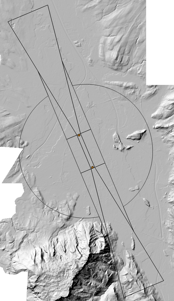
Figure 1: Obstacle Detection Area.
Approach
The obstacles data can be obtained by using intersection of a raster which modeled the safety zone and with the DSM. The safety zone are modeled as vector data which then rasterized. after the intersection with DSM has been done, the raster file will be vectorized and can be used as obstacle data.
Python Implementation
Data Preparation
The first part of the modeling is the preparation of the points that are being used in the safezone planes. starting with the two points that corresponds to the runway, we use height from the points or use height information from the DTM. for this purpose we use opalsImport to get the points. If we decide to use DTM as points' heights then we use Module AddInfo to add height information from grid file (DTM) into the ODM z component
imp = Import.Import()
imp.inFile = axis_file
imp.outFile = axisODM
imp.run()
imp = None
if not point_height:
logger.verbose("Loading point height from DTM")
addin = AddInfo.AddInfo()
addin.inFile = axisODM
addin.gridFile = dtm_file
addin.attribute = "_z=r[0]"
addin.run()
addin = None
inDM = DM.Datamanager.load(axisODM, True, False)
lf = DM.AddInfoLayoutFactory()
lf.addColumn(DM.ColumnType.double_, "_z")
layout = lf.getLayout()
apts = []
for p in inDM.points(layout):
if point_height:
apts.append(np.array([p.x, p.y, p.z]))
else:
apts.append(np.array([p.x, p.y, p.info().get(0)]))
if abs(p.info().get(0) - p.z):
print (
"point height : {}\ndtm height : {}".format(
p.z, p.info().get(0)))
inCRS = inDM.getCRS()
logger.verbose("CRS\t"+inCRS)
inDM = None
pts = np.vstack(apts)
Model Creation
We use two points from axis file as starting points to refer to both end of the airport's runway
A = pts[0, :]
B = pts[1, :]
mid = 0.5 * (A + B)
height_ref = mid[2]
and calculate direction vectors to compute safety zone vertices
strip_length_3d = np.linalg.norm(B - A)
strip_length_2d = np.linalg.norm(B[:2] - A[:2])
dir = (B[:2] - A[:2]) / strip_length_2d
dir2d = np.array([dir[0], dir[1], 0])
dir3d = (B - A) / strip_length_3d
dir_perp = np.array([dir[1], -dir[0]])
dir_perp_3d = np.array([dir[1], -dir[0], 0])
here are the constant parameters used for constructing safety zone vertices
parallel_offset = 60.
perp_offset = 150
side_ramp_offset = 850.
far_ramp_parallel_length = 10000.
far_ramp_perp_length = 1500.
far_ramp_height = 120.
side_ramp_height = 10.2
parallel_inclination = 1.2 / 100.
perp_inclination = 1.2 / 100.
side_ramp_height_difference = side_ramp_offset * perp_inclination
far_ramp_parallel_height_difference = far_ramp_parallel_length * parallel_inclination
max_far_ramp_height_difference = 100.
max_side_height_difference = 45.
side_radius_flat = 5100.
side_radius_ramp = 5100.
Point Modeling
we start by constructing extension of the starting points outward 30 meters each
A_ = A - dir3d * parallel_offset
B_ = B + dir3d * parallel_offset
then we compute points perpendicular to the runway
A_L = A_ - dir_perp_3d * perp_offset
A_R = A_ + dir_perp_3d * perp_offset
B_L = B_ - dir_perp_3d * perp_offset
B_R = B_ + dir_perp_3d * perp_offset
then we compute points in the tilted plane on each side of the runway
A_LL = A_L - dir_perp_3d * side_ramp_offset + \
np.array([0, 0, side_ramp_height_difference])
A_RR = A_R + dir_perp_3d * side_ramp_offset + \
np.array([0, 0, side_ramp_height_difference])
B_LL = B_L - dir_perp_3d * side_ramp_offset + \
np.array([0, 0, side_ramp_height_difference])
B_RR = B_R + dir_perp_3d * side_ramp_offset + \
np.array([0, 0, side_ramp_height_difference])
we continue with computing tilted plane in the direction of aircraft departure and arrival
A_L1 = A_L - dir2d * far_ramp_parallel_length - dir_perp_3d * \
far_ramp_perp_length + np.array([0, 0, far_ramp_parallel_height_difference])
A_R1 = A_R - dir2d * far_ramp_parallel_length + dir_perp_3d * \
far_ramp_perp_length + np.array([0, 0, far_ramp_parallel_height_difference])
B_L1 = B_L + dir2d * far_ramp_parallel_length - dir_perp_3d * \
far_ramp_perp_length + np.array([0, 0, far_ramp_parallel_height_difference])
B_R1 = B_R + dir2d * far_ramp_parallel_length + dir_perp_3d * \
far_ramp_perp_length + np.array([0, 0, far_ramp_parallel_height_difference])
to fill in the hole gap between tilted plane on the side and tilted plane in the departure/arrival, we compute the intersection points
A_L0, al0ratio = get_intersect(A_L, A_L1, A_LL)
A_R0, ar0ratio = get_intersect(A_R, A_R1, A_RR)
B_L0, bl0ratio = get_intersect(B_L, B_L1, B_LL)
B_R0, br0ratio = get_intersect(B_R, B_R1, B_RR)
Polygon Construction
dm = DM.Datamanager.create(inFile, False)
dm.setCRS(inCRS)
f = DM.PolygonFactory()
if draw_runway_plane:
f.addPoint(*A_L)
f.addPoint(*A_R)
f.addPoint(*B_R)
f.addPoint(*B_L)
f.closePart()
p1 = f.getPolygon()
dm.addPolygon(p1)
f.addPoint(*B_LL)
f.addPoint(*A_LL)
f.addPoint(*A_L)
f.addPoint(*B_L)
f.closePart()
p2 = f.getPolygon()
dm.addPolygon(p2)
f = DM.PolygonFactory()
f.addPoint(*A_R)
f.addPoint(*A_RR)
f.addPoint(*B_RR)
f.addPoint(*B_R)
f.closePart()
p3 = f.getPolygon()
dm.addPolygon(p3)
f = DM.PolygonFactory()
f.addPoint(*A_L)
f.addPoint(*A_L1)
f.addPoint(*A_R1)
f.addPoint(*A_R)
f.closePart()
p4 = f.getPolygon(DM.Orientation.ccw)
dm.addPolygon(p4)
f.addPoint(*B_R)
f.addPoint(*B_R1)
f.addPoint(*B_L1)
f.addPoint(*B_L)
f.closePart()
p5 = f.getPolygon()
dm.addPolygon(p5)
f.addPoint(*A_L)
f.addPoint(*A_LL)
f.addPoint(*A_L0)
f.closePart()
p6 = f.getPolygon()
dm.addPolygon(p6)
f.addPoint(*A_R)
f.addPoint(*A_R0)
f.addPoint(*A_RR)
f.closePart()
p7 = f.getPolygon()
dm.addPolygon(p7)
f.addPoint(*B_L)
f.addPoint(*B_L0)
f.addPoint(*B_LL)
f.closePart()
p8 = f.getPolygon()
dm.addPolygon(p8)
f.addPoint(*B_R)
f.addPoint(*B_RR)
f.addPoint(*B_R0)
f.closePart()
p9 = f.getPolygon()
dm.addPolygon(p9)
Obstacle Detection
Obstacles are detected by intersecting rasterized safety zone model with DSM and DTM
alg.reset()
alg.inFile = [step2File, dsm_file]
alg.outFile = intersectFile
alg.formula = "return r[1]-r[0] if r[0] is not None and r[1]-r[0]>1 else None"
alg.limit = "dataset:0"
alg.run()
alg.reset()
alg.inFile = [step2File, dtm_file]
alg.outFile = intersectDtmFile
alg.formula = "return r[1]-r[0] if r[0] is not None and r[1]-r[0]>1 else None"
alg.limit = "dataset:0"
alg.run()
Since opalsContouring only supports 8-bit raster file, The intersected file needs to be converted. This can be done using opalsShade which can also used as Visualization.
shd = Shade.Shade()
shd.inFile = intersectFile
shd.outFile = intersectShade
shd.run()
from opals import Contouring
cnt = Contouring.Contouring()
cnt.inFile = intersectShade
cnt.outFile = obstacleFile
cnt.run()
Result

Figure 2: Output of obstacle detection on DTM.
shd.reset()
shd.inFile = step2File
shd.sunPosition = (350, 95)
shd.run()
cnt.reset()
cnt.inFile = step2Shade
cnt.outFile = regionFile
cnt.run()
opals_step_log()
shd.reset()
shd.inFile = step1File
shd.sunPosition = (350, 95)
shd.run()
References
 1.8.17