Technische Universität Wien
Orientation and Processing of Airborne Laser Scanning data
Department of Geodesy and Geoinformation - Research Groups Photogrammetry and Remote Sensing
The OPALS Datamanager (ODM) is key component of OPALS. It has been developed for efficient access to huge spatial data sets and for handling arbitrary attributes capsulated to geometry objects.
Efficient data handling is a precondition for today's LIDAR processing software. Even large ALS projects have to be processable in an appropriate amount of time. The ODM therefore tackles the requirement of huge data set handling (points in the order of 10^9 can be administered), but also, the support of multi-threaded processing tools.
The spatial indexing concept of the ODM considers the geometry data properties of ALS campaigns. Points are the primary data source, however, line and polygon geometries (i.e. structure lines, vegetation layers, building boundaries, etc.) have to be handled as well. To achieve maximum performance, the ODM splits point data and more complex geometry objects into two separated spatial indices.
The point data are organized in a hierarchical structure with two levels. The level 0 index can be seen as matrix which partitions space into 2-dimensional tiles. An appropriate tile size is automatically determined during import (also see Module Import). Per default the first 0.2 million points are used to estimate the point density. Then the tile size is computed such that 0.2 million points hit one tile in average. For tile structure insert operations and spatial queries are straight forward and very fast in execution.
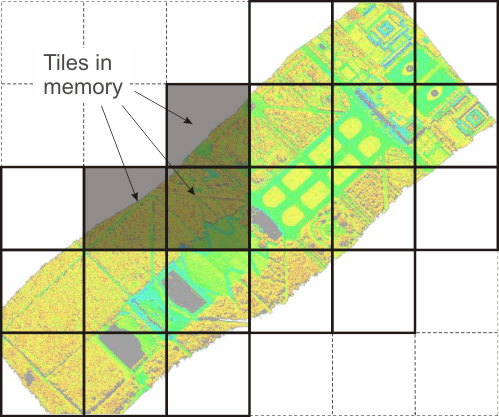
In general the amount of point data clearly exceeds the physical available memory of today's computer. Therefore the ODM provides a spatially oriented swapping strategy based on the tiling structure. Tiles are always fully loaded up to a certain limit of points in memory (per default 5 million points). If new tiles are requested into memory the manager objects unloads disposable tiles from the end of a recent used list.
The level 1 index is responsible for indexing points within one tile. Since tiles are always fully loaded into memory level 1 indices do not require swapping functionality. The ODM does not read and write the actual level 1 index structure from/to file. Tests have shown that on-the-fly index building is equally fast to reading a full index structure if the number of points stays below a certain limit. This has two advantages:
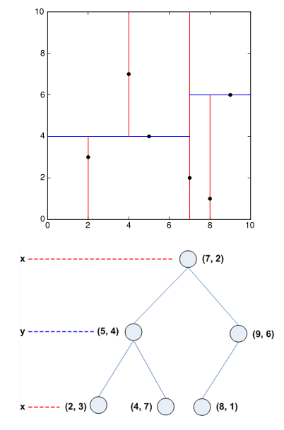
Currently the ODM only uses kD-Trees (Bentley, 1975) for level 1 indexing. The kD-Tree, a generalisation of a binary search tree, is an extremely fast spatial indexing method. This static indexing structure only supports point data, but its speed for nearest neighbor search and range queries is outstanding. The use implementation is based on the kD-Tree class of CGAL (see Third party software).
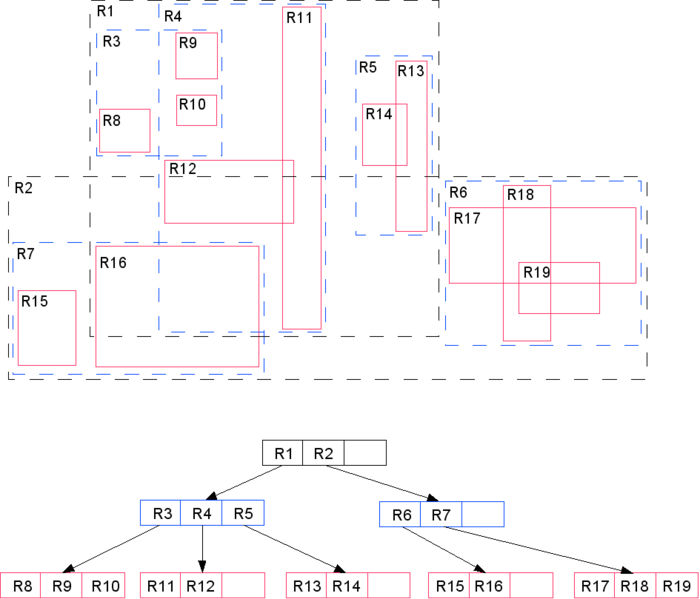
For line and polygon data the ODM uses a R*-tree (Beckmann et al., 1990) for spatial indexing. Each object is represented by its bounding box within the tree. The R*-tree splits space into hierarchically nested, and possibly overlapping, k-dimensional boxes. Using a special heuristic it is tried to minimize both, coverage and overlap of the boxes. The use implementation is based on the R*-Tree class of SpatialIndex (see Third party software)
After importing a data set into the ODM, opalsImport reports an index statistics as shown below (The same statistics can be retrieved at any time using the opalsInfo). Altough the automatic tile size estimation is robust against outliers, it is assumed that the point density of the first 0.2 million points is representative for the overall data set. Since the point density of LiDAR data is usually quite homogeneous the tile size estimation is usually non-crucial. In case the homogeneous assumption does not hold (e.g. for terrestrial laserscanning data) or for strange point arragment the tile size estimation algorithm may fail to select an appropriate value, which can cause problems in the subsequent processing (see FAQ). Hence, it is important to understand and interpret the reported index statistics correctly.
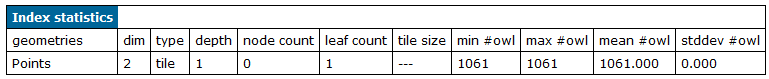
Since the ODM has different indicies for point and polygon data, two table rows are be listed if geometries of both types are stored within the ODM. The spatial index statistics informs about the index type, the maximum depth of the data structure (is always one is case of tiling), the number of nodes (node count) and leafs (leafs count), the tile size in case of an tiling structures and some statistic parameters (min #owl, max #owl, mean #owl and stddev #owl) about the number of objects within leafs (#owl). The differentiation between nodes and leafs is coming from the terminology of data structures. A node (also known as an internal node, inner node or branch node) does have childeren, whereas, leafs (also known as an external node, outer node, leaf node, or terminal node) doesn't have any childeren. Within most data structures (like the ODM) the data itself are managed in leafs only. In case of the tiling structure of the ODM, the node count repesents the number of elements of the tile matrix and leafs count the number of tiles that contain point data. if node count is zero (c.f. Figure 4) the ODM is not in tiling mode yet.
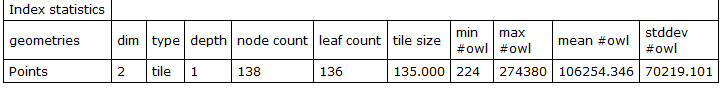
The second index statistics example (see Figure 5) comes from a flight strip containing approx. 15 mio points. For this data set an average approx. 100000 points are stored within one tile and the maximum number of points per tile is less than 300000. These are optimal values regarding processing speed and small index overhead. Since various OPALS modules perform parallel processing based on the tiling structure, a high number of points per tile can lead to problems while processing since tiles are always completly loaded into memory. The mean #owl should be below 0.3 mio points and the maximum #owl should not exceed 0.6 mio points. Otherwise, 'Unable to load new data tiles' exceptions may occur in case of high core environments (>= 8). The problem can be partly compensated by the global parameter -points_in_memory allow allocating more memory during processing or reducing the number of processing threads (see common parameter -nbThreads). However, it is recommended to re-import the data set with a smaller tile size (see Module Import parameter -tileSize) in case of doubt.
For optimal spatial performance the ODM organises and stores data in spatial order as described above. Hence, the natural order of the data gets lost. Although this is irrelevant for most applications, situations can arise where it is necessary to preserve natural order of the data. The ODM structure provides an additional index for storing the data order, which allows to export the data in the original import order. ATTENTION: This feature is not available yet
Handling arbitrary attributes for each geometry object is the second key feature of the ODM. This make each odm file comparable to a database table. Therefore nearly any file format can be repesented loss-free within the ODM. In general, attributes can be divided into two different groups
Predefined attributes have fixed names and data types. From a module point of view those attributes have a well-defined semantic (and unit). Some OPALS modules (ie. Module Normals, Module EchoRatio, ...) use predefined attributes as input and/or for storing computational results.
User-defined attributes, on the other hand, are intended to store OPALS irrelevant information or information that doesn't match predefined attributes. Such attributes can be identified by a prefixing '_' (underscore) character. ODM supports a wide range of different data types which are freely choosable for user-defined attributes, see DM::ColumnType :
| Enumerator | Name | Size | Minimum | Maximum | Comment |
|---|---|---|---|---|---|
| DM::ColumnType::int8 | int8 | 1 byte | -128 | 127 | signed integer |
| DM::ColumnType::uint8 | uint8 | 1 byte | 0 | 255 | unsigned integer |
| DM::ColumnType::int16 | int16 | 2 bytes | -32,768 | 32,767 | signed integer |
| DM::ColumnType::uint16 | uint16 | 2 bytes | 0 | 65,535 | unsigned integer |
| DM::ColumnType::int32 | int32 | 4 bytes | -2,147,483,648 | 2,147,483,647 | signed integer |
| DM::ColumnType::uint32 | uint32 | 4 bytes | 0 | 4,294,967,295 | unsigned integer |
| DM::ColumnType::int64 | int64 | 8 bytes | -9,223,372,036,854,775,808 | 9,223,372,036,854,775,807 | signed integer |
| DM::ColumnType::float_ | float | 4 bytes | -3.402823466e+38 | 3.402823466e+38 | real |
| DM::ColumnType::double_ | double | 8 bytes | -1.7976931348623158e+308 | 1.7976931348623158e+308 | real |
| DM::ColumnType::bool_ | bool | 1 bit | false; 0 | true; 1 | logical |
| DM::ColumnType::string | string | variable | — | — | variable length string |
| DM::ColumnType::cstr | cstr(n) | n bytes | — | — | fixed length string |
For a describition how to define user-defined attributes during import please see Module Import, OPALS Generic Format, and LAS Format Definition. A full list of all predefined attributes can be found here.
For completeness it should be mentioned that predefined, but also, user-defined attributes can be used to filter the full data set during processing (for details see generic filter)
Each ODM file contains a small file table storing meta information about each imported file. Additional the ODM attaches to each geometry object the corresponding file id (attribute FileId). Hence, the original (multiple) import files can be reproduced export using Module Export.
The ODM imports full data information, but also, tries to represent the data structure using layers. The layer concept, as it is known from CAD software, is useful to group and organise the data in a specific way. Therefore ODM provides a layer table for each file. E.g. the layer structure of LAS file is based on the classification field. By retrieving the file and layer id (attribute LayerId) of objects the corresponding layer object entry can be accessed.
File and layer tables are automatically created during import. Up to now, OPALS does not provide tools to manipulate those information. However, the FileId and LayerId attribute of each geometry object can be used for filtering and processing the data.
| Name | Type | Comment |
| Amplitude | float | Linear scale value proportional to the receiving power |
| Attribute | uint8 | |
| BeamVectorX | float | X-component of beam vector (from scanner to point) |
| BeamVectorY | float | Y-component of beam vector (from scanner to point) |
| BeamVectorZ | float | Z-component of beam vector (from scanner to point) |
| Blue | uint16 | Blue colour channel |
| ChannelDesc | uint8 | |
| Classification | uint8 | See LAS spec |
| ClassificationFlags | uint8 | See LAS spec |
| Confidence | uint8 | |
| ConstrainedFlag | bool | |
| CrossSection | float | |
| CumulativeDistance | float | See Riegl POF Format Spec.) |
| CurveParam | float | |
| CustomClassId | uint8 | |
| EchoNumber | uint8 | This is the k-th return/echo for a certain pulse, where for the first return: k==1 (see LAS spec.) |
| EchoRatio | float | |
| EchoWidth | float | Full width at half maximum [ns] |
| EchoWidthNormalised | float | |
| EdgeOfFlightLine | bool | |
| Estimator | uint8 | |
| FaceId | uint32 | triangle faces id |
| FileId | uint16 | |
| GPSTime | double | |
| Green | uint16 | Green colour channel |
| Id | int64 | |
| InfraRed | uint16 | Infrared (IR) colour channel |
| KappaAngle | float | [radians] Rotation angle as defined by ORIENT |
| LASExtensions | string | |
| LayerId | uint16 | |
| MarkedFlag | bool | |
| MaxCurvature | float | |
| MaxCurvatureDirection | float | |
| MinCurvature | float | |
| NormalEigenvalue1 | float | Highest eigenvalue of normal estimation covariance matrix |
| NormalEigenvalue2 | float | Second highest eigenvalue of normal estimation covariance matrix |
| NormalEigenvalue3 | float | Third highest eigenvalue of normal estimation covariance matrix |
| NormalEstimationMethod | uint8 | Normal estimator id (0...simple, 1...robust, 2...FMCD) |
| NormalLeftX | float | x value of normal vector left to a structure line |
| NormalLeftY | float | y value of normal vector left to a structure line |
| NormalLeftZ | float | z value of normal vector left to a structure line |
| NormalPlaneOffset | float | Offset from the current point to the estimated local plane |
| NormalPtsGiven | uint8 | Number of points given to the normal estimator |
| NormalPtsUsed | uint8 | Number of points used in the normal estimator |
| NormalRightX | float | x value of normal vector right to a structure line |
| NormalRightY | float | y value of normal vector right to a structure line |
| NormalRightZ | float | z value of normal vector right to a structure line |
| NormalSigma0 | float | Sigma0 of normal estimation |
| NormalX | float | x value of normal (unit) vector |
| NormalY | float | y value of normal (unit) vector |
| NormalZ | float | z value of normal (unit) vector |
| NormalizedZ | float | point height above DTM |
| NrOfEchos | uint8 | The pulse which this point is based on generated this number of returns/echoes (see LAS spec.) |
| OmegaAngle | float | [radians] Rotation angle as defined by ORIENT |
| PanAngle | float | [radians] Rotation of scanner head around primary axis of scanner. In case of a 1-D scanner, this is the varying angle around the only axis of the scanner. |
| PhiAngle | float | [radians] Rotation angle as defined by ORIENT |
| PitchAngle | float | [radians] as defined by the aviation norm ARINC 705 |
| PointCode | string | general alphanumeric point code |
| PointLabel | string | |
| PointSourceId | uint16 | |
| RGIndex | uint16 | |
| Range | float | |
| Red | uint16 | Red colour channel |
| Reflectance | float | |
| Residual | float | |
| RollAngle | float | [radians] as defined by the aviation norm ARINC 705 |
| ScanAngle | float | [radians] Scan angle as defined by LAS standard: Angle between the nadir vector and the projected beam vector. Therefore, the beam vector is projected into a vertical plane that is orthogonal to the horizontal flight direction. The angle is 0 for nadir, negative to the left side (and positive to the right side) of the aircraft in flight direction. |
| ScanDirection | bool | |
| ScopSemantic | int32 | |
| SegmentID | uint32 | unique segment id |
| SegmentPtsUsed | int32 | Number of points contributing to a single segment |
| SigmaNormalFit | float | |
| SigmaX | float | |
| SigmaY | float | |
| SigmaZ | float | |
| SpreadAngle | float | |
| StructNr | uint16 | |
| TangentSigmaX | float | |
| TangentSigmaY | float | |
| TangentSigmaZ | float | |
| TangentX | float | |
| TangentY | float | |
| TangentZ | float | |
| TiltAngle | float | [radians] Rotation of scanner head around secondary axis of scanner (fixed angle for 1-D scanners) |
| UltraViolet | uint16 | Ultraviolet (UV) colour channel |
| UserData | uint8 | |
| VertexId | uint32 | |
| WaterDepth | float | Water depth of a submerged (bathymetric lidar) point |
| WinputCode | uint16 | |
| X0 | double | Exterior reference point as defined by ORIENT |
| Y0 | double | Exterior reference point as defined by ORIENT |
| YawAngle | float | [radians] as defined by the aviation norm ARINC 705 |
| Z0 | double | Exterior reference point as defined by ORIENT |
The OPALS distribution comes along with a ODM API (Application Programmable Interface) for C++ and Python. The library provides a low level acccess to ODMs as it is used by the OPALS modules. For details please refer to the C++ Datamanager library (DM) or the Python bindings of the Datamanager library (pyDM).
 1.8.17