Module Shade
See also
opals::IShade

Aim of module

Derives shaded relief raster maps (geo-coded hill shading) of DEM grids.

General description

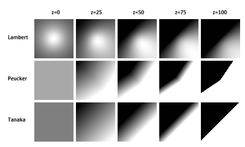
Hill shading is a method to visualize a surface grid model by illuminating it using a light source shining from a certain direction. Artificial shadows are calculated depending on the slope (steepness) and exposition of the surface w.r.t the direction of the light source. Depending on the artificial shadow length, grey values (0=shaded..255=exposed) are assigned to each cell of the output raster.

See also
Module Shade

To derive a shaded relief map an input grid model file is needed (parameter inFile). The resulting shaded image (parameter outFile) is stored as a regular grid in one of the Raster formats for visualization (parameter oFormat). The main calculation parameters are the position of the virtual light source (parameter sunPosition, azimuth and zenith angle) and the shading method. The following shading algorithms (parameter shading) are provided:

  • Tanaka: This method is based on the idea of a terraced model of the terrain which is illuminated by a light source. The calculation of the luminance is based on the ratio of illuminated to shadowed areas. This method gives good results except when the light source is at the zenith.
  • Lambert: With this method the terrain is assumed to be an ideal lambertian reflector. The luminance is proportional to the cosine of the angle beetween the surface normal and the direction vector to the light source. Drawback of this method: Areas exposed to the light source get brighter with increasing slope, but get darker when the zenith angle of the slope's normal increases above the zenith angle of the light source.
  • Peucker: For the standard case (light source in north west) this method is a piecewise linear approximation of the method based on lambertian reflection. It avoids the effect of areas getting darker with increasing slope (parameter sunPosition has no effect in this case).
Parabolic basin illuminated from north-west with varying zenith angles z

By default, the output grid is constructed according to the structure of the input grid (reference point, cell size, and number of columns and rows). However, a user defined output cell size can be defined (parameter pixelSize). User defined XY-limits (parameter limits) can either refer to the centers (=default) or corners of the outermost pixels (c.f. limit parameter description).

The slope values to be used for shading calculation must be estimated from the height values of the grid points. The estimated slope values are located in the center of 4 adjacent grid points. If XY-limits are not specified, then the estimated slope values will be used directly for the shading calculation, and therefore the resulting image is one column and one row smaller than the input grid. If parameters limits and/or pixelSize are specified, a bilinear resampling of the slope values will take place before the shading calculation.

Estimating slope values from heights can be avoided if corresponding grid features were derived with Module Grid. normalx/normaly or slope/exposition may be used alternatively as inputs using parameter feature. In this case, the resulting image will be the same size as the input grid if pixelSize is not specified.

Parameter description

-inFileinput grid model file(s)
Type: opals::Vector<opals::Path>
Remarks: mandatory
Specifies the input grid model file(s).
-featurethe grid feature(s) that inFile represent(s)
Type: opals::Vector<opals::GridFeature::Enum>
Remarks: default=height
Possible values:  
  slope ........ steepest slope [%] (deprecated: use slpPerc instead)
  slpPerc ...... steepest slope [%]
  exposition ... slope aspect [rad] (deprecated: use expoRad instead) 
  exposRad ..... slope aspect [rad] (azimuth of steepest slope)
  normalx ...... x-component of surface normal unit vector
  normaly ...... y-component of surface normal unit vector
  height ....... surface height
Either specify both normalx and normaly, both slope and exposition, or only height. The number of features must correspond to the number of inFiles
-outFileoutput raster file
Type: opals::Path
Remarks: estimable
Shaded raster map file name.
Estimation rule: The current directory and the name (body) of the input file are used as file name basis.
-oFormatoutput file format (e.g. GTiff, PNG, etc.)
Type: opals::String
Remarks: estimable
Output file format (GDAL driver name). Supported formats: GeoTiff, JPEG, PNG, PNM, GIF, BMP, XPM...
Estimation rule: estimated from file extension if not specified.
-pixelSizepixel size of output raster image
Type: float
Remarks: estimable
Edge length of one pixel in the resulting raster image.
Estimation rule: default value = model grid size.
-limit2D clipping window
Type: opals::GridLimit
Remarks: optional
If no user defined limits are specified or -limit is even skipped, the entire xy-extents of the grid model are used.
GridLimit: Defines xy-limits for output grid/raster datasets. The limit coordinates specified by left/lower/right/upper either refer to pixel centers (default) or corners, and may optionally get rounded to multiples of the grid size.
Syntax: ['center'|'corner']['round']['(' left lower right upper ')']
-shadingshading method
Type: opals::ShadingMethod
Remarks: default=tanaka
Possible values:  
  tanaka .... use algorithm according to Tanaka
  lambert ... lambertian reflection (proportional to cosine of incident angle)
  peucker ... lambertian reflection (approximation according to Peucker)
Method to be used for shading the model.
-sunPositionsun position (azimuth, zenith angle - both measured in gon)
Type: opals::Array<double, 2>
Remarks: default=350 50
Position of the light source illuminating the model.
-createAlphacreate alpha channel
Type: bool
Remarks: default=0
Flag if an alpha channel mask should be created. This is useful in conjunction with lossy compression since a nodata mask based on a specific value might be incorrect due to compression losses.

Examples

First we will use the following commands to generate a DSM from a subset of the ALS point cloud of strips G111, G112 and G113 using only a minimum set of parameters.

opalsImport -inFile G111.las G112.las G113.las -outFile GAll.odm -filter "Region[-2100 338850 -1900 339040]"
opalsGrid -inFile GAll.odm -outFile dsm.tif -interpolation movingPlanes -gridSize 0.5 -searchRad 2.5

Now we can use Module Shade to compute hill shadings from this DSM using the following commands. We specify the input grid, the resulting raster image file, the shading algorithm, and the virtual sun position.

opalsShade -inFile dsm.tif -outFile dsm_shd_tan_350_50.tif -shading tanaka -sun 350 50
opalsShade -inFile dsm.tif -outFile dsm_shd_peu_350_50.tif -shading peucker -sun 350 50
opalsShade -inFile dsm.tif -outFile dsm_shd_lam_350_50.tif -shading lambert -sun 350 50
opalsShade -inFile dsm.tif -outFile dsm_shd_tan_050_75.tif -shading tanaka -sun 50 75
opalsShade -inFile dsm.tif -outFile dsm_shd_peu_050_75.tif -shading peucker -sun 50 75
opalsShade -inFile dsm.tif -outFile dsm_shd_lam_050_75.tif -shading lambert -sun 50 75
DSM hill shadings: Tanaka (left), Peucker (center), Lambert (right); Illumination: NW (350/50), NE (50/75)

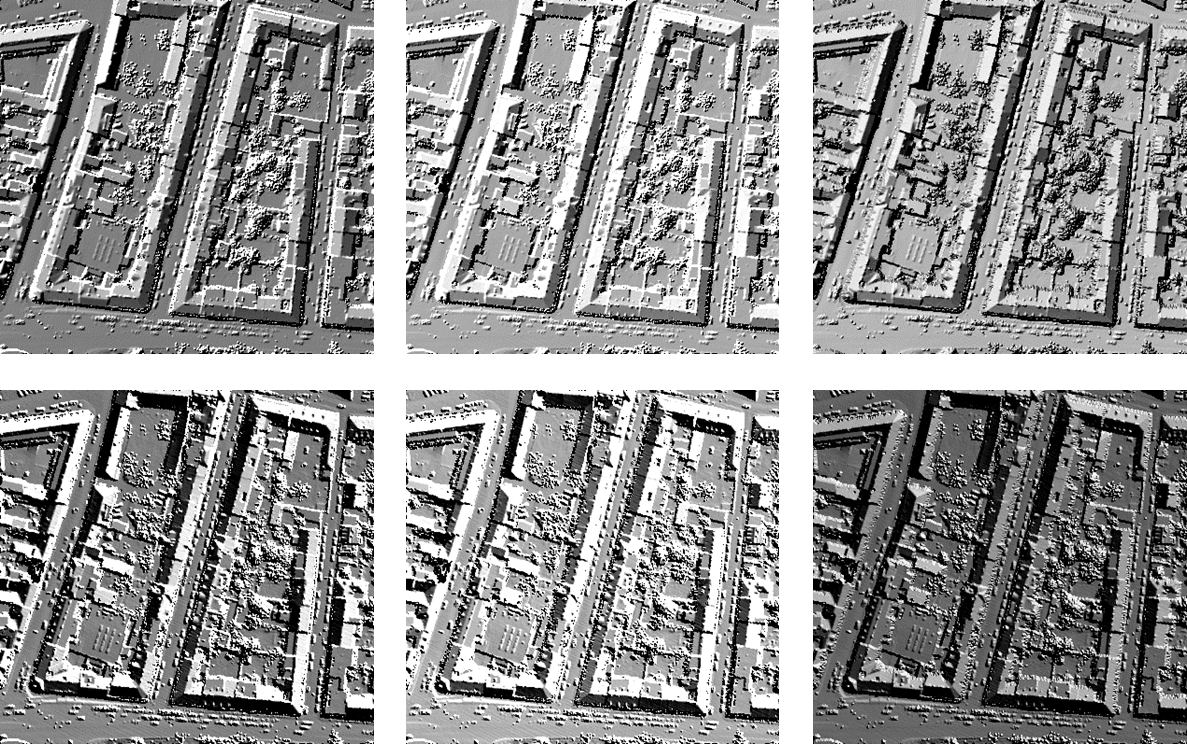
Alternately, we may use grid features normalx/normaly or slope/exposition as input.

opalsGrid -inf GAll.odm -outFile dsm.tif -feature normalx normaly -interpolation movingPlanes -gridSize 0.5 -searchRad 2.5
opalsShade -inf dsm_nx.tif dsm_ny.tif -feature normalx normaly -outFile dsm_nvec_shd.tif
opalsGrid -inf GAll.odm -outFile dsm.tif -feature slpPerc exposRad -interpolation movingPlanes -gridSize 0.5 -searchRad 2.5
opalsShade -inf dsm_slpPerc.tif dsm_exposRad.tif -feature slpPerc exposRad -outf dsm_slope_shd.tif

References

Horn, B. K. P., "Hill Shading and the Reflectance Map," In: Proc. IEEE vol. 69, . 14–47, Jan 1981

Ecker, R., 1984, "Höhencodierung, Gefällsstufendarstellung und Schummerung aus einem DHM mit dem Optronics", Diplomarbeit, Institut für Photogrammetrie und Fernerkundung, TU Wien

@ tanaka
use algorithm according to Tanaka
@ movingPlanes
moving (tilted) plane interpolation
@ normalx
x-component of surface normal unit vector
Definition: GridFeature.hpp:23
@ shading
shading algorithm (opalsShade)
opalsImport is the executable file of Module Import
Definition: ModuleExecutables.hpp:113
@ normaly
y-component of surface normal unit vector
Definition: GridFeature.hpp:24
@ slpPerc
steepest slope [%]
Definition: GridFeature.hpp:17
@ exposRad
slope aspect [rad] (azimuth of steepest slope)
Definition: GridFeature.hpp:21
opalsGrid is the executable file of Module Grid
Definition: ModuleExecutables.hpp:93
@ filter
string to be parsed in construction of DM::IFilter (various modules)
@ lambert
lambertian reflection (proportional to cosine of incident angle)
@ feature
Use a statistic feature of the boundary gap points for filling.
@ peucker
lambertian reflection (approximation according to Peucker)
opalsShade is the executable file of Module Shade
Definition: ModuleExecutables.hpp:198