Technische Universität Wien
Orientation and Processing of Airborne Laser Scanning data
Department of Geodesy and Geoinformation - Research Groups Photogrammetry and Remote Sensing
Performs range and refraction corrections of raw laser bathymetry measurements according to Snell's law.
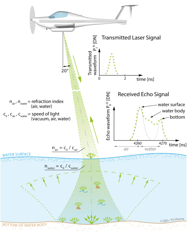
Airborne laser bathymetry (ALB) is the technique for measuring the depths of relatively shallow coastal or inland waters (rivers, ponds, lakes). ALB is a two-media measurement process, since the laser beam has to travel both through the air and the water. This propagation, though, presents some differences between the air and the water, the main of which is in the propagation velocity of the laser beam (i.e. the speed of light). For that reason, the laser echoes that penetrate into the water column, need to be corrected due to this effect.
More specifically, according to the principle of ALB, a short green laser pulse ( \(\lambda = 532 nm\)) is emitted from an airborne platform, travels through the atmosphere, and hits the water surface where it gets refracted towards the plumb line. Within the water column the laser beam propagates with reduced velocity and is scattered at water and sediment particles. A part of the signal is reflected from the bottom of the water body, and, after the return trip, the full waveform of the backscattered echo signal is detected at the receiver. Beam refraction as a consequence of the different propagation speed in air and water is described by Snell's law (Willebrord Snellius) as:
\[ \frac{\sin\vartheta_{air}}{\sin\vartheta_{water}} = \frac{c_{air}}{c_{water}} = \frac{n_{water}}{n_{air}} \]
where \(\vartheta_{air}\) is the incidence angle of the laser beam w.r.t. the normal vector of the water surface and \(\vartheta_{water}\) in the water, \(c_{air}\) and \(c_{water}\) are the group velocities in the air and the water respectively and finally \(n_{air}\) and \(n_{water}\) are the refractive indices in the air and the water at the respective wavelength. It is mentioned that the refractive index of clear water at 20 °C is 1.33.
The interaction of the green laser beam with the medium water is illustrated in Fig. 1.
The range and refraction correction is carried out for the points of the input OPALS Datamanager (inFile). For each point, the laser beam is intersected with the water surface model (refModel), which may either be provided as a grid file in GDAL supported format or as a constant height value. A useful tool to obtain a water surface model is the Python script Water Surface Modelling Tool (see qpals WaterSurfaceModeler). All points intersecting the water surface are corrected applying Snell's law, as described above, based on the specified refraction index (refracIndex). Optionally, a filter (filter) can be used to restrict the considered point set.
Please note, that intersecting the laser beam with the water surface model requires storage of the beam vector. Therefore, the ODM file must contain the following attributes for all water echoes:
For all bathymetric echoes the x/y/z-coordinate offsets and the water depth are stored as additional attributes in the ODM:
Furthermore the classification of the bathymetric echoes is set to ASPRS Standard LIDAR Point Class 9 (i.e. water). If an optional output file (outFile) is specified the range/refraction corrected coordinates and all attributes are written to a new OPALS Datamanager.
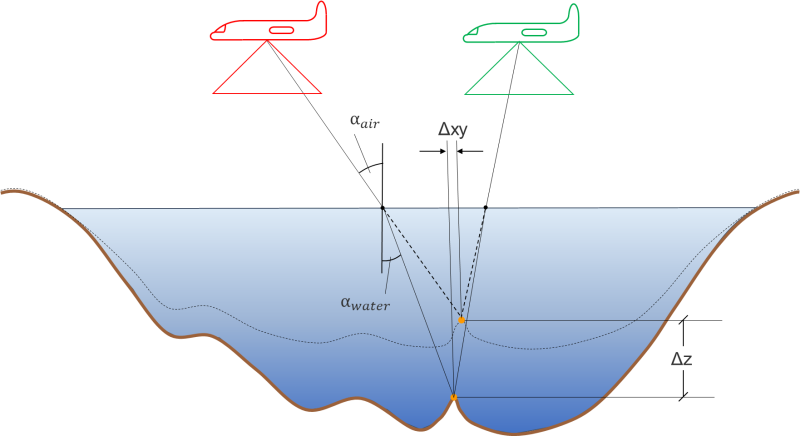
Module Snellius cannot only be used for laser bathymetry but also for photo bathymetry. Fig. 2 shows a principle sketch of image ray refraction in the multimedia photogrammetric case. As in laser bathymetry, ray bending is described by Snell's law.
The input file (inFile) contains the uncorrected photogrammetric 3D point cloud. To activate the photogrammetric mode, a file (oriFile) containing the exterior orientations of the photos from which the point cloud was derived must be specified. Please note that for proper photo bathymetry refraction correction, only the camera positions (X, Y, Z) are required but not the rotation angles. Arbitrary file formats are supported via parameter oriFormat. Please refer to OPALS Format Definition for further information about user defined file formats.
As in the laser case, the coordinate corrections as well as the water depth are stored as additional attributes (cf. above). As the bended image rays are generally skew, additional accuracy measures describing the the quality of the ray forward intersection are provided:
The data used in the following examples can be found in the $OPALS_ROOT/demo/ directory.
This first example gives guidance on how the opalsSnellius module can be used for the range/refraction correction of the raw, uncorrected laser point cloud. A brief description of the required files is also included. For further investigation of the opalsSnellius module as well as the Python script Water Surface Modelling Tool, see the use case Airborne Laser Bathymetry application: Range/Refraction correction at Pielach River, Austria.
To perform range/refraction correction of a raw ALB point cloud run the following commands:
The raw ALB point cloud is contained in the strip149.las, while with the LAS_1.4_beamInfo.xml XML file (OPALS Format Definition) its format is specified. Note that the water surface model is already provided as a raster model stored in GeoTiff format while usually it has to be generated from the data.
If the parameter (outFile) is specified, the range/refraction corrected coordinates (X, Y and Z) are stored in the new ODM together with all additional attributes of the input ODM. Please note that the intermediate attributes _REFCORRX, _REFCORRY and _REFCORRZ are not contained in the output ODM.
To compute and visualize the differences, run the following command sequence:
At first, the two DEMs are created, for the raw and the corrected point cloud respectively. Using the opalsAlgebra, the difference between these two is computed and saved into a new .tif file (diff.tif), which is shown in Fig. 3.
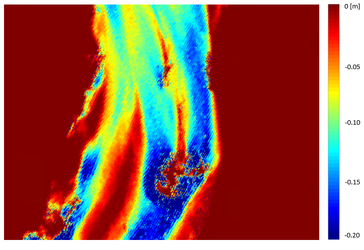
It is observed that all of the differences are negative, which implies that the corrected points have higher values of Z, and therefore smaller depths, as expected. This is due to the fact that the raw water depths are overestimated as a matter of not considering the reduced propagation speed of light in water. In addition, the dark red regions, that have a zero value, are non water regions. So, there were no corrections applied to them.
Another way to visualize the differences is by using the opalsSection module or the Python script sectionDemo.py included in the $OPALS_ROOT/demo/ directory:
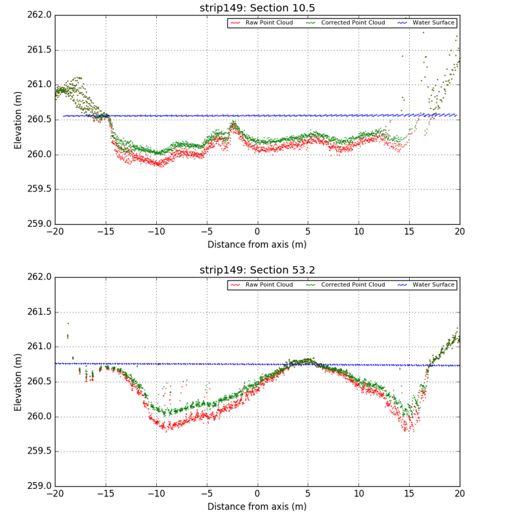
Fig. 4 shows the two point clouds with respect to the water surface, as that was extracted from the water surface model. It is obvious that when the points are over the water surface, the two different datasets coincide since there is no range correction. In addition, one can see that the range/refraction corrections are higher in deeper waters.
As stated in the general description, in laser bathymetry different refractive indices apply for the angular component (beam deflection) and the range (signal runtime). If a second refractive index is provided, this one is used for the range correction. To demonstrate the effect, a (physically implausible) refractive index of 1.8 is used in the following example.
The differences between the corrected points from Fig. 4 and the points calculated with refractive index of 1.8 considering the velocity can be seen in Fig. 5.

The second example illustrates refraction correction of a photogrammetric point cloud. In addition to the 3D points, the water surface model and the image positions/orientations are required.
The results are plotted in Fig. 6:
Mandlburger, G., Pfennigbauer, M., & Pfeifer, N. (2013). Analyzing near water surface penetration in laser bathymetry – A case study at the River Pielach. ISPRS Ann. Photogramm. Remote Sens. Spatial Inf. Sci. ISPRS Annals of Photogrammetry, Remote Sensing and Spatial Information Sciences, II-5/W2, 175-180. doi:10.5194/isprsannals-ii-5-w2-175-2013
Mandlburger, G., Hauer, C., Wieser, M., Pfeifer, N. (2015). Topo-Bathymetric LiDAR for Monitoring River Morphodynamics and Instream Habitats - A Case Study at the Pielach River. Remote Sens. 2015, 7, 6160-6195.
 1.8.17