Technische Universität Wien
Orientation and Processing of Airborne Laser Scanning data
Department of Geodesy and Geoinformation - Research Groups Photogrammetry and Remote Sensing
Calculates a land cover dependent DSM raster model based on the approach of Hollaus et. al. (2010).
In contrast to the algorithms for determining digital terrain models (DTMs) from Airborne Laser Scanning (ALS) data, those for the generation of Digital Surface Models (DSMs) are rather straightforward. A common way to derive DSMs is the determination of the highest point within a defined raster cell (DSMmax) or the determination of the DSM heights based on moving least squares interpolation e.g. moving planes (DSMmls). For low ALS point densities void pixels can occur in the DSMmax and for inclined smooth surfaces the DSMmax shows artificial roughness mainly due to the irregular point distribution. These disadvantages of the DSMmax can be reduced by using an interpolated DSMmls grid. On the other hand, the DSMmls introduces smoothing effects along surface discontinuities e.g. building borders, tree tops, forest gaps, etc. Module DSM therefore implements a combined approach for DSM generation making use of the strengths of, both, the DSMmax and the DSMmls (Hollaus et al., 2010).
Starting with the 3D point cloud stored in a single or multiple OPALS Datamanger (ODM) files as basic input (inFile) the final DSM (outFile) is derived as a regular grid (gridSize) and stored in a GDAL (GeoData Abstraction Library) supported format (oFormat). In general, the entire point cloud is used for processing but, however, the input data set can be restricted by specifying an appropriate filter string (filter). As stated above, the main idea is the calculation of (i) a raster containing the highest elevation within a raster cell (DSMmax) and (ii) a (smooth) surface grid derived via moving planes interpolation. For the latter the definition of a proper neighbourhood is required. Module DSM hereby uses a generation based neigbourhood defined by the desired number of data points (neighbours) used for plane fitting constrained by a maximum search distance (searchRadius). The point selection strategy is illustrated in Figure 1.
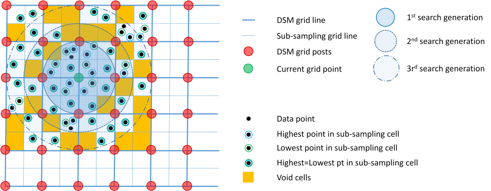
The generation based point selection works as follows. First, a sub-sampling grid is constructed (thin blue lines) such that each grid cell of the final DSM (thick blue lines and red circles, respectively) is composed of four sub-sampling grid cells. Within each cell of the sub-sampling grid the highest point is determined (black point surrounded by blue circle) and stored as the representative point of this cell. As a by-product also the lowest points are detected and and stored (black points surrounded by green circles). Depending on the point density and point distribution, some of the sub-sampling cells may not contain points and, thus, are marked as void. Please note, that although the (highest) points are now organized in a raster, allowing fast nearest neighbour point queries, still the original points with their arbitrary 3D positions and attributes are maintained. To interpolate the height of a specific grid point (green circle), the k-nearest neigbouring points are queried from the sub-sampling raster (highest points per cell) in a generation based manner. The first generation contains all cells whose cell centers are located in a circle with a radius equal to the DSM grid size. If the number of valid data points is less than the requested neighbour count (neighbours) the search radius is extended by the size of the sub-sampling grid (i.e. half of the DSM grid size). All (cell) points of the resulting circular ring (i.e. 2nd generation) are added. The procedure is repeated unit either the requested neighbour count or the maximum search radius is reached. The DSMmls grid height is subsequently interpolated by fitting a tilted plane (cf. Module Grid for further details). The DSMmax height, in turn, is strictly derived from the four sub-sampling grid cells sorrounding the grid point by selecting the highest cell. The DSMmax grid cell remains void if all four adjactent sub-sampling grid cells are void. The DSM height for the current position is finally obtained by choosing either the height of DSMmax or DSMmls, respecively, depending on the local surface roughness (maxSigma). The latter is obtained as a by-product of the moving planes interpolation. The DSMmax is chosen if a valid maximum height exists at the current location and if the local sourface roughness is greater than the specified threshold, otherwise the DSMmls is used. For more details please refer to Hollaus et al., 2010.
The specification of user defined limit window (limit), and a user defined void marker identifying invalid cells in the DSM output grid (noData) is optional. By default, the intermediate products (min, max, mls, sigma models) are stored as separate files on the disk. If, however, parameter multiBand is specified, the output file is constructed as a multi-band raster file containing the DSM (i.e. first band) and all intermediate rasters.
The data used in the following examples can be found in the $OPALS_ROOT/demo/ directory. As a prerequisite import the data (strip??.laz) into an OPALS data manager using the following command:
Using the default values, a DSM raster in 1m-resolution can be derived with:
Please note, that in addition to the DSM raster (dsm.tif) additional intermediate raster products (max/min/movingPlanes/sigma0/pointCount-models) are created.
More examples coming soon ....
Hollaus, M., Mandlburger, G., Pfeifer, N., Mücke, W., 2010. Land cover dependent derivation of digital surface models from airborne laser scanning data. PCV 2010, Paris; in: "IAPRS Volume XXXVIII Part 3A", ISSN: 1682-1750; 221
 1.8.17