Creates a TIN surface from ODM vector data based on a 2D constrained Delaunay triangulation.
Module TIN performs a triangular tesselation of the plane, using input data points (including line points) as vertices. These vertices are connected by edges to form a triangulation following the Delaunay criterion, unless there are incident edges considered as constraints. Module TIN allows for the creation of triangular irregular networks (TINs) based on input data, and the export of those TINs into various data formats. Also, alpha-shapes may be derived, and the valid region(s) be extracted.
Specify the ODM and/or data files to be triangulated using parameter inFile. The file format(s) may be specified explicitly using parameter iFormat. Module TIN allows for filtering the input data using parameter iFilter. It processes the import of certain data types particularly, as mentioned in the following subsections.
As a consequence of the triangulation generated by module TIN being 2-dimensional, only 1 triangulation vertex can be created for any planar position. For data points with the same planar coordinates, module TIN creates a vertex for the first imported point only, and ignores the subsequent points to be imported (leaving the existing vertex' z-coordinate and eventual attributes unchanged). For that reason, the number of triangulation vertices may be smaller than the number of imported data points.
For any lines to be imported, module TIN creates a triangulation vertex for each line vertex, and inserts constrained triangulation edges for each line segment. Constrained triangulation edges are preserved even if they violate the Delaunay criterion. At every 2-d intersection of constrained edges, module TIN inserts an additional vertex with mean z-coordinate.
Module TIN caches lines with general semantic, 2-dimensional data, and lines with border semantic separately during import. It inserts only other data into the triangulation directly, while it fills the 3 caches for the mentioned data types. These caches are processed only after importing all input data files, in a predefined order:
If any line with border semantic cannot be merged into a line that encircles a closed region (i.e. a polygon), module TIN issues an error. Otherwise, module TIN considers the regions enclosed by those lines as valid regions of the resulting TIN, and regions outside those lines as invalid TIN regions. If no lines with border semantic have been imported, then module TIN considers the whole (planar) area of the TIN as valid.
When merging lines (considering parameter snapRadius), the z-coordinates of line (end) points to be merged are averaged.
The resulting TIN may be exported using parameter outFile. Kindly note, however, that only a few file formats allow for storing the TIN topology. All other vector formats will either export the triangular faces as separate polylines (e.g. format ESRI Shape), or merely the triangulation vertices as points (e.g. format XYZ). The data to be exported may be filtered using parameter oFilter.
The resulting TIN's valid regions may be exported using parameter borderFile.
Finally, module TIN allows for the export of an \(\alpha\)-shape of the resulting triangulation using parameter alphaShape. For an explanation of \(\alpha\)-shapes, see Module Bounds. Compared to the export of an \(\alpha\)-shape using module TIN, Module Bounds provides the advantage of a possibly much smaller memory consumption and faster processing. Kindly note that exporting an \(\alpha\)-shape of a triangulation that contains constrained edges may lead to unexpected results.
All data used in the following examples are located in the $OPALS_ROOT/demo/ directory of the OPALS distribution.
Running the command:
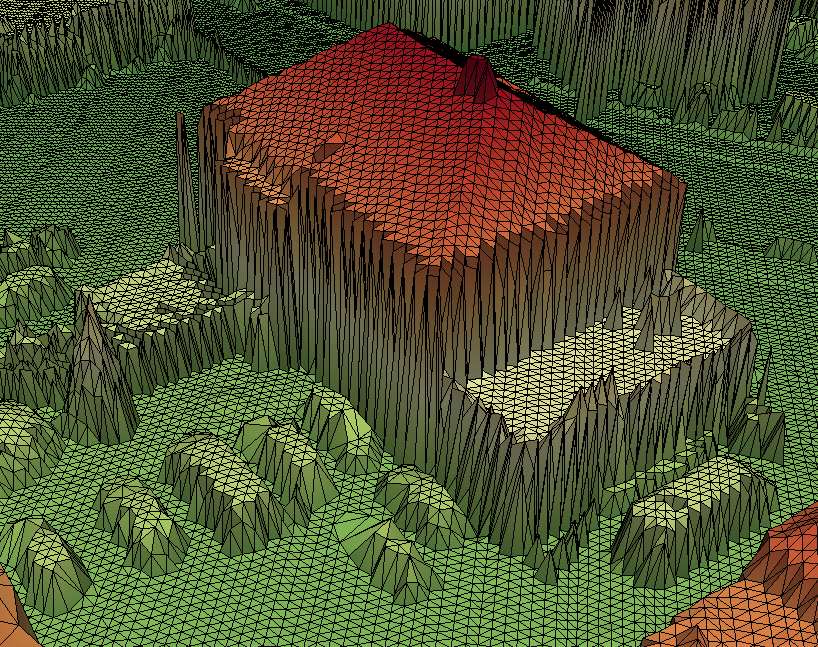
... results in the demo data set strip11.laz being triangulated, and the TIN topology being exported to file strip11.wrl . Using ParaView, the following visualization can be generated. For numeric reasons, parameter oFilter has been used to reduce the planar coordinates.
