- See also
- opals::ILSM
Aim of module
Estimates an affine 3D transformation to align overlapping ALS strip DEMs using Least Squares Matching.
General description
Least-squares matching (LSM) is a traditional photogrammetric technique for establishing the correspondence of (aerial or terrestrial) images taken from different view points. In Module LSM, this technique is applied to ALS surface models (DSM/DTM) in regular grid structure. The basic idea of LSM is to find the corresponding location of a surface patch inside a window of one dataset in another dataset. This is achieved by estimating the parameters of a predefined type of transformation so that the difference between the two datasets inside the patch are minimized. Whereas the patch size is limited to small windows in case LSM is applied to images (due to different viewing directions and the perspective image projection), much bigger areas can be used for the investigation of two overlapping ALS strips because the strip surface models represent an orthogonal projection (thus, each strip has the same viewing direction). This even enables the derivation of quasi-continuous 3D-shifts along the flight path of approximately parallel ALS strips covering the entire strip overlap area.
The basic input for Module LSM are the surface grid files of two overlapping ALS strips (parameter inFile) and, optionally, corresponding binary grid mask files (parameter gridMask) indicating areas which should not be used during LSM (due to vegetation and/or occlusion). Grid masks can be derived by means of module Module Algebra. The following figure illustrates the effect of using grid masks for the LSM computation.
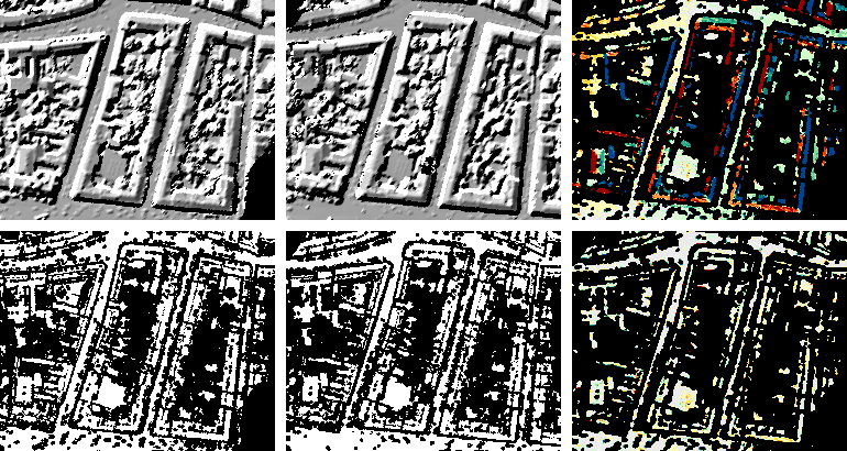
Top left/centre: DSM (shading) and corresponding grid mask of the first strip. Bottom left/centre: DSM (shading) and corresponding grid mask of the second strip. Right: (colour-coded) masked z-differences before (top) and after (bottom) applying the 3D-shifts determined by LSM.
The transformation being used for LSM can be described by the 3x4-matrix \(\mathbf{T}=\begin{pmatrix}1+a & b & c & d \\ e & 1+f & g & h \\ i & j & 1+k & l \end{pmatrix}\) and the reduction point \(\mathbf{p_0}=\begin{pmatrix}x_0 \\ y_0 \\ z_0 \end{pmatrix}\).
Splitting \(\mathbf{T}\) into \(\mathbf{A}=\begin{pmatrix}1+a & b & c \\ e & 1+f & g \\ i & j & 1+k \end{pmatrix}\) and \(\mathbf{t}=\begin{pmatrix}d \\ h \\ l \end{pmatrix}\), we can denote the transformation equation as follows:
\[\mathbf{p'}=\mathbf{A}(\mathbf{p}-\mathbf{p_0})+\mathbf{t}+\mathbf{p_0}\]
\(\mathbf{p}=\begin{pmatrix}x & y & z \end{pmatrix}^T\) is the point given in the system of the dataset to be moved ('mov'), whereas \(\mathbf{p'}=\begin{pmatrix}x' & y' & z' \end{pmatrix}^T\) is the same point given in the system of the fixed dataset ('fix').
There are three transformation types (parameter lsmTrafo) that can be used for LSM computation:
-
shifts: Only the 3 translation components \(d\), \(h\) and \(l\) are estimated, whereas the remaining 9 parameters are kept constant at 0.
-
mounting: The 3 translation components and 3 flight-direction-aligned rotation parameters (i.e. alltogether 6 independent parameters) are estimated. In this case, the transformation matrix is \(\mathbf{T}=\begin{pmatrix}1 & b & c & d \\ 0 & 1 & g & h \\ 0 & -g & 1 & l \end{pmatrix}\). Depending on the flight strips' azimuth, rotation angles ('roll', 'pitch', 'yaw') may be reconstructed from the parameters \(b\), \(c\) and \(g\).
-
full: All 12 parameters \(a\) to \(l\) are estimated, i.e. a full affine 3D transformation is computed.
Module LSM can be run in three different modes (parameter lsmMode):
-
local: The LSM computation is performed for a set of patches (independently of each other). From a spot data file (parameter spotData), distinct 2D positions - representing the centres of the patches - are read. Using the parameter patchSize, the dimensions dx and dy of the rectangular patches may be specified (if only one value is specified, quadratic patches of size dx are used). For each patch, an individual transformation parameter set is estimated.
-
continuous: The patches are arranged along the flight direction (which is estimated from the input datasets or manually set using the direction parameter). The patch length (i.e. the dimension measured along the flight direction) may be specified, whereas the patch width (i.e. the dimension measured perpendicularly to the flight direction) is automatically calculated in such a way that the entire cross-overlap area of the two strips is covered. The parameter patchSize is interpreted in a different way than in the local mode: The first value specifies the patch length, whereas the second value defines the overlap (given in %) of successive patches. It must not exceed 99% and may be negative (in this case, gaps between successive patches occur). For each patch, an individual transformation parameter set is estimated.
-
global: The LSM computation is performed for the entire cross-overlap area of the two strips yielding one single global transformation parameter set.
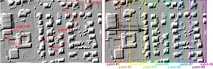
Left: patches in local mode. Right: patches in continuous mode with an overlap of 20%
As reference point \(\mathbf{p_0}\), the centre of gravity of the respective patch (local and continuous mode) or of the entire area (global mode) is used. Beside the estimated LSM parameters, respective error metrics are derived. The results may be stored in an XML file (parameter outParamFile).
Parameter description
-inFile1st and 2nd input grid model file
Type:
opals::Array<
opals::Path, 2>
Remarks: mandatory
Specifies the two input grid model files in GDAL supported format as basis for the LSM computation. The grid models must overlap in order to obtain reasonable results. The 1st grid model is 'fixed' while the 2nd grid is 'moved' in order to find the best fitting position and orientation with respect to the 'fixed' model applying a 3D affine transformation.
-gridMask1st and 2nd grid mask file
Type:
opals::Array<
opals::Path, 2>
Remarks: optional
Specifies the two grid mask files in GDAL supported format, each corresponding to the respective grid model input file (inFile). Grid masks are used to mark (un)usable areas (e.g. due to surface roughness and/or occlusion).
-spotDataspot data file (2D-pos for LSM computation)
Type:
opals::Path
Remarks: optional
The spot data file contains 2D positions for which an LSM computation should be carried out. Currently, it has to be provided as opals data manager (ODM) file. This parameter is only considered in case of local processing mode (lsmMode=local).
-outTrafParsoutput transformation parameters
Type:
opals::Vector<
opals::TrafPars3dAffine>
Remarks: output
The results of the LSM computations are the 12 parameters of an 3D affine transformation.
lsmMode=local: a separate parameter set is returned for each 2D-location (spotData).
lsmMode=continuous: a separate parameter set is returned for each patch along the flight path.
lsmMode=global: a single parameter set is returned for the entire strip overlap area.
TrafPars3dAffine: Describes a relative or absolute 3D-affine transformation. This class contains the transformation parameters of an affine 3D (i.e. 12-parameter) transformation, given as 12-array -lsmTrafotransformation type
Type:
opals::LSMTrafoType
Remarks: default=full
Allows to specify the type of the transformation used for LSM computation.
-lsmModeprocessing mode
Type:
opals::LSMProcMode
Remarks: default=global
Depending on the processing mode either a single transformation is estimated for the entire overlap area of two strips (lsmMode=global) or multiple transformations are calculated for delimited parts (lsmMode=local|continuous).
-robFactorfactor for robust parameter estimation
Type: float
Remarks: default=6
-patchSizesize of LSM window
Type:
opals::Vector<double>
Remarks: estimable
Specifies the size of the LSM window. lsmMode=local: size of window as dx[,dy], lsmMode=continuous: size of window along the estimated flight direction as dx[,longitudinal overlap in %], the lateral (y-)dimension (perpendicular to the flight direction) is automatically calculated based on the overlap area of the strip pair. Please note, that patchSize is not considered in case of lsmMode=global.
Estimation rule: 49*grid width (contin. mode: longitudinal overlap=70%)
-directiondirection for continuous mode
Type:
opals::Vector<double>
Remarks: optional
In case of the continuous lsm mode, the computation requires a (flight) direction. It can be automatically determined by the module (averaged long side of the minimum bounding rectangle of both input grids) or manually specified in two different ways.
one value: angle value in degree
two values: 2d direction vector
-maxMemorymaximum RAM memory [MB]
Type: int32
Remarks: default=1000
Specifies the maximum amount of RAM memory to be used by the module.
-maxItermaximum number of iterations
Type: int32
Remarks: default=10
The affine transformation parameters are calculated iteratively. Starting with the identity transformation the parameters are refined in each iteration until the parameter updates are below a threshold or the maximum number of iterations is reached.
Examples
The data used in the following example can be found in the $OPALS_ROOT/demo/ directory. As input datasets, the grid models strip21.tif and strip11.tif are used, which have been created from strip21.laz and strip11.laz by using Module Import and Module Grid :
In the first example the full 3D affine transformation is estimated for the entire strip overlap area without using grid masks.
After the maximum number of iterations (here: default value of 10), one obtains \(\mathbf{A}=\begin{pmatrix} ~~1.00081 & -0.00041 & -0.00845 \\ ~~0.00031 & ~~1.00060 & ~~0.02096 \\ -0.00005 & ~~0.00027 & ~~0.99780 \end{pmatrix}\) and \(\mathbf{t}=\begin{pmatrix}-0.825 \\ ~~0.074 \\ ~~0.026 \end{pmatrix}\).
The following output is written to the file lsm_output.xml:
...
AffineTrafo3D[
IdGridFix[strip21.tif]
IdGridMov[strip11.tif]
TrafPars[
+1.00081 -0.00041 -0.00845 -0.82538
+0.00031 +1.00060 +0.02096 +0.07387
-0.00005 +0.00027 +0.99780 +0.02591]
RefPointFix[32511263 5525600 170]
RefPointMov[32511263 5525600 170]
Sigma0[0.06508]
NrObs[49773]
Qxx[
+1.19e990 99.82e992 +3.40e990 -5.52e990 +2.83e992 -4.02e992 +4.78e991 +4.18e991 -6.77e994 -3.07e993 99.98e991 +6.30e991
99.82e992 +2.91e990 +2.77e990 99.90e990 -3.06e992 +1.13e991 -5.95e992 -9.42e991 -3.06e993 +1.06e993 99.02e991 99.27e991
+3.40e990 +2.77e990 +1.02e-07 99.63e-07 +3.23e991 998.51e991 +3.65e-09 -4.31e-09 -3.36e991 -9.65e992 -4.77e991 +2.92e990
-5.52e990 99.90e990 99.63e-07 +1.16e-06 +8.22e992 -9.85e991 -4.50e-09 +3.42e-08 +1.22e990 +8.37e992 +7.57e990 +9.09e990
+2.83e992 -3.06e992 +3.23e991 +8.22e992 +9.99e991 +2.15e991 -3.96e990 99.04e-09 +3.43e993 998.22e993 +2.09e991 +5.65e991
-4.02e992 +1.13e991 998.51e991 -9.85e991 +2.15e991 +2.32e990 998.37e990 998.87e991 +2.37e994 -3.99e994 +1.58e991 +5.85e991
+4.78e991 -5.95e992 +3.65e-09 -4.50e-09 -3.96e990 998.37e990 +7.48e-08 99.15e-07 -6.21e992 +3.41e992 -8.11e990 -4.52e-09
+4.18e991 -9.42e991 -4.31e-09 +3.42e-08 99.04e-09 998.87e991 99.15e-07 +9.55e-07 +2.63e992 +2.13e991 998.62e-09 +6.32e-09
-6.77e994 -3.06e993 -3.36e991 +1.22e990 +3.43e993 +2.37e994 -6.21e992 +2.63e992 +1.00e991 99.63e993 +5.24e991 +5.54e991
-3.07e993 +1.06e993 -9.65e992 +8.37e992 998.22e993 -3.99e994 +3.41e992 +2.13e991 99.63e993 +2.62e991 +2.72e991 -4.87e991
99.98e991 99.02e991 -4.77e991 +7.57e990 +2.09e991 +1.58e991 -8.11e990 998.62e-09 +5.24e991 +2.72e991 +8.45e-09 +3.90e-09
+6.30e991 99.27e991 +2.92e990 +9.09e990 +5.65e991 +5.85e991 -4.52e-09 +6.32e-09 +5.54e991 -4.87e991 +3.90e-09 +8.74e-08
]
...
Note: For better readability, the values extracted from the XML result file have been rounded to 5 decimal places (trafPars and sigma0) and 3 significant digits (Qxx), respectively.
References
Ressl, C., Kager, H. and Mandlburger, G., 2008. Quality checking of ALS projects using statistics of strip differences. In: IAPRS, XXXVII, pp. 25399860.
Ressl, C., Mandlburger, G. and Pfeifer, N., 2009. Untersuchungen zur Verbesserung der Georeferenzierung von ALS-Streifen ohne Verwendung von GNSS-IMU-Trajektoriendaten. In: "Vorträge 29. Wissenschaftlich-Technische Jahrestagung der DGPF - 'Zukunft mit Tradition'", 18 (2009), ISSN: 0942998870; S. 365 - 375.
Ressl, C., Mandlburger, G. and Pfeifer, N., 2009. Investigating Adjustment Of Airborne Laser Scanning Strips Without Usage Of GNSS/IMU Trajectory Data. In: "ISPRS Workshop Laserscanning `09", IAPRS, Vol. XXXVIII, Part 3/W8 (2009), ISSN: 168299750; pp. 195 - 200.
 1.8.17