Technische Universität Wien
Orientation and Processing of Airborne Laser Scanning data
Department of Geodesy and Geoinformation - Research Groups Photogrammetry and Remote Sensing
Performs vector-to-raster conversion for all types of simple feature geometries (points, lines, polygons).
The main functionality of this module is to create a raster file from an ODM input file. The rasterizing process is a 2D operation where fixed or variable values are written to the output raster at the 2D location of the geometry objects. Per default a fixed value of 1 is used to 'burn' the geometries into the output raster. Variable burn values can either be the z values of the objects or attribute values that were attached to the geometry objects. Use parameter attribute to specify a fixed value or the corresponding attribute name.
The output file must be a format that is supported by GDAL (c.f. parameter oFormat)
This module burns all geometries types (points, polylines and polygons) into the first raster band of the output file. Whereas polylines represent linear structure, polygons describe areas resulting in filled raster objects (see figures below). In case of overlapping objects, the value of the last geometry will be stored in the output raster.
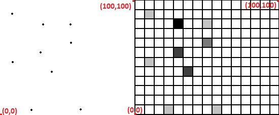
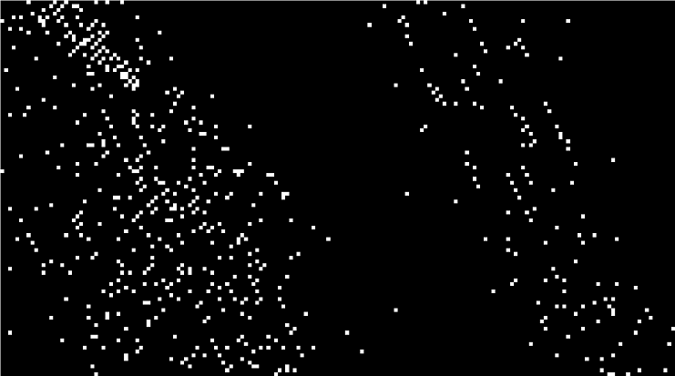
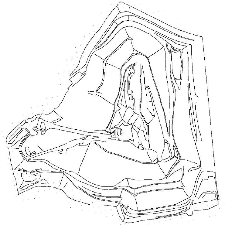
The following image shows a simple point to raster conversion. Different colours represent different z values of the rasterized points. If the raster is binary (default) the raster pixels will be 0 or 1. The Example 1 shows an raster image of a small LiDAR dataset.
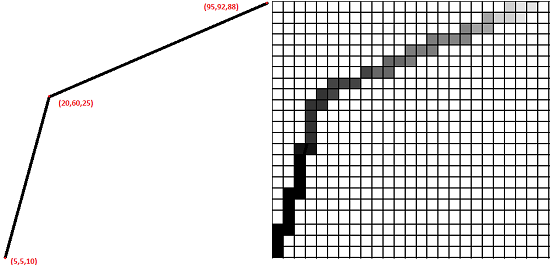
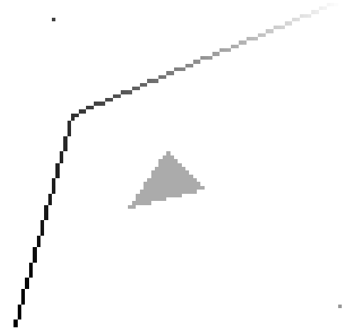
Whereas Module Cell can be equally used for rasterzing point coulds, the rasterize module is also able to rasterize polylines. Polyline rasterization with defined attribute is shown in the following image. The shown polyline is defined by three points. The module interpolates between the line vertices in a linear manner.
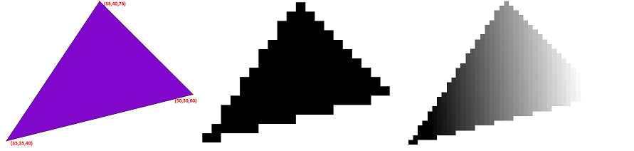
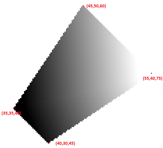
As it can be seen below, polygons can also be rasterized by the module. Whereas rasterization of polylines with attribute z is straight forward, things get complicated for polygons since it's not directly possible to linear interpolate value for pixel inside the polygons. The implemented algorithm builds a Constraint Delaunay Triangulation from the polygon and rasters relevant triangles. Doing so it is possible to linear interpolate value for the inside pixels. The following figure shows a simple polygon using fixed value (centre) or variable values (right) burning.
The cellSize is a mandatory field that the user has to input according to the precision that the user needs. The user must provide one or two double values as the raster cell size (one value results in squared pixels). The raster extents are either derived automatically based on the (xy-) extents of input data or can be specified by the user limit. Optionally, a value indicating data voids noData can be defined.
In some cases it is useful to consider only a subset of the data, e.g. to rasterize all last echoes only. For this purpose, OPALS provides a general concept for filtering input data (parameter filter). See here for details.
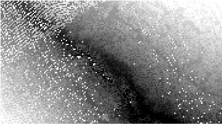
Example 1: Rasterize point cloud file filled with points
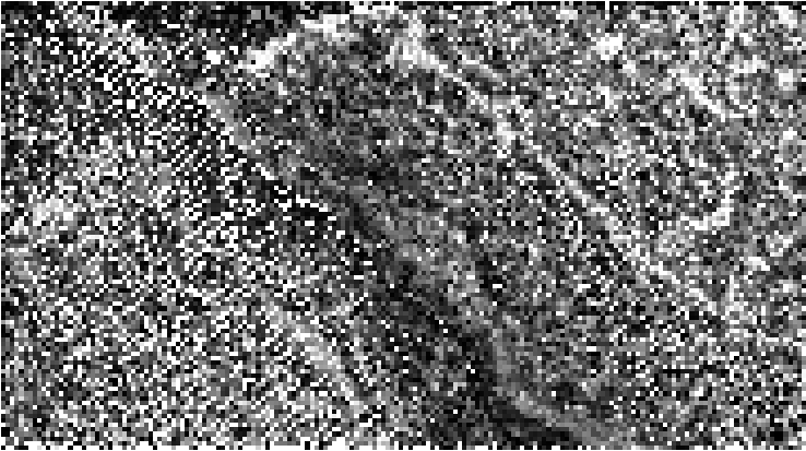
Executing the above command will create the file fullwave.tif. According to the command syntax the cell size is 1 x 1 and the attribute used is Z (i.e. elevation).
Example 2: Rasterize point cloud file filled with points
Executing the above command will export the file fullwave.tif. According to the command syntax the cell size is 1*1 and there is no specific attribute set, which means that the raster file will use binary values as Z value.
Without using any attribute, if it's not necessary, will reduce the execution time and the file size also.
Example 3: Example Using different attribute and Filter
The example above shows the difference when using different attribute and the filter functionality. For more detailed information about pre-selecting data please refer to the Filter manual.
Example 4: Rasterize point cloud file filled with polygons
In the following screenshot three polygons are converted to raster polygons.The image of the left shows the vector polygon within the odm file
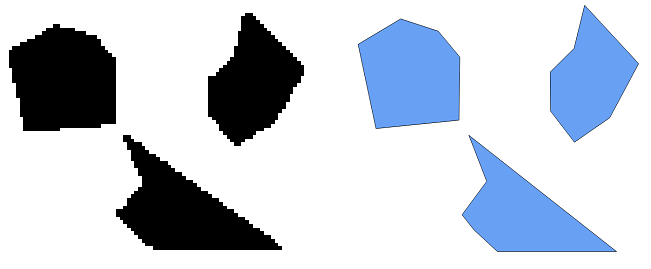
Changing the cellSize will improve the resolution of raster image, but will increase the output file size and will increase the execution time of the Rasterize Module. In this example the execution time is not critical because the files are very small but using larger files the difference in execution time is obvious and not trivial.
Example 5: Rasterize point polygons with given limits
The following image shows the rasterize module output using limit parameter. As shown in the image when a polygon is in between the limits,the part which is inside the limit is rasterized only. The following image could be compared with the images in Example 3.
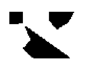
This option helps the user to rasterize only the area that is interested in. The polygons or other geometry division is handled automatically by the module.
Example 6: Rasterize point cloud file filled with multilines and points
Example 7: Different geometry types within one file The following example creates an ODM containing two points, a polyline and a polygon using the pyDM python package. Then, the vector data are rasterized.
Example 8: Polygon and variable burn values The following example demonstrates a file that consists of a polygon and which is rasterized using z as variable burn values. Like points and polylines the cells different colour of points in the polygon file shows that the z value is different from cell to cell. In this example we select the cell size 0.5 to increase the accuracy of the output raster file.
 1.8.17