Module GeorefApprox
See also
opals::IGeorefApprox

Aim of module

Improves the geo-referencing of an ALS flight block based on pairwise affine strip transformations (cf. Module LSM).

General description

The Module GeorefApprox allows to perform the geo-referencing of a set of ALS strips so that they are finally given in one common coordinate system. Therefore, a multi-strip adjustment is carried out where the pairwise relative orientation parameters resulting from a previous step are used as observations (e.g., this can be done by applying Module LSM to each overlapping strip pair).

The basic input for Module GeorefApprox is a list of relative transformation parameters as obtained by Module LSM. Of course, all ALS strips occurring in this list must be connected to each other by relative transformations (otherwise, multi-strip adjustment will fail). By default, all those strips will be used in adjustment. However, the user may define a subset of strips by specifying the parameter stripList.

In order to define the datum, 12 parameters are chosen and kept fixed. Therefore, one of the strips is declared as reference strip. By default, the most central strip - i.e. the strip whose centre of gravity (COG) is closest to the median position of all strips' COGs - is determined and selected as reference strip. However, a user-defined reference strip may be specified using the parameter fixedStrip.

The simplest way to define the datum is to keep one complete transformation-set fixed, i.e. to set the reference strip's transformation to identity transformation. In this case, however, residual errors stemming from the mounting calibration may - when performing adjustment without any control features - cause a shift which is linearly growing for each strip with its (across-flight-direction) distance from the central fixed strip.

Effect of a yaw error of the mounting calibration. The three strips S1, S2 and S3 are flown meandering in east-west direction. (a) shows the strips in the reference system in case of error-free orientation. (b) shows the situation after introducing an yaw error of the mounting calibration. (c) shows the situation after strip adjustment (allowing only one 3D shift per strip), where the central strip is kept fixed and used as reference strip. The figure is taken from (Ressl et al., 2009)

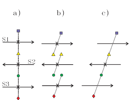
In order to prevent the block from this 'affine drifting', zero-shift observations are introduced for the two peripheral strips (i.e. 6 shift components are observed 0). In this case, the datum definition requires 6 further constraints: therefore, it is sufficient that 2 rotation angles, 2 scales and 2 affinities are kept fixed in the reference strip's transformation.

The parameter sigmaShift specifies the standard deviation of additional zero-shift observations (recommended value: some dm). If sigmaShift = 0, no such observations are introduced to the adjustment and the identity transformation is assigned to the reference strip in order to fix the datum. If a positve value is specified, the additional shift observations apply to the two outermost strips of the block. In case sigmaShift is negative, the fictional zero-shift observations are applied to all strips of the block.

Parameter description

-obsTrafParsobserved relative transformation parameters
Type: opals::Vector<opals::TrafPars3dAffine>
Remarks: optional
Specifies a list of relative strip transformation parameters usually determined by Module LSM. The transformation parameters are introduced as observations in a global strip adjustment. Secure that all strips are connected by relative transformations (no separated strip block) otherwise the adjustment will fail.
TrafPars3dAffine: Describes a relative or absolute 3D-affine transformation. This class contains the transformation parameters of an affine 3D (i.e. 12-parameter) transformation, given as 12-array
-outTrafParsoutput transformation parameters
Type: opals::Vector<opals::TrafPars3dAffine>
Remarks: output
The results of the strip adjustment are the 12 parameters of an 3D affine transformation of each strip.
TrafPars3dAffine: Describes a relative or absolute 3D-affine transformation. This class contains the transformation parameters of an affine 3D (i.e. 12-parameter) transformation, given as 12-array
-stripListoptional strip list
Type: opals::Vector<opals::Path>
Remarks: estimable
Per default all strips defined in the obsTrafPars list are used in the strip adjustment. In case of a given strip list only specified strips are processed. Estimation rule: All strips referenced in trafPars are used for the stripList.
-fixedStripfixed strip within the adjustment
Type: opals::Path
Remarks: estimable
Specifies which strip is fixed (reference strip) within the strip adjustment. Estimation rule: The most central strip given in stripList or trafPars (i.e. the strip having its centre of gravity closest to the median position of all used strips) is chosen as reference strip.
-sigmaShiftsigma of additional shift observations
Type: double
Remarks: default=-0.1
Specifies a sigma of artificial zero shift observations to avoid affine shifting caused by 'error propagation'. If sigmaShift == 0, additional shift observations are omitted (sigmaShift is set to zero).
If sigmaShift > 0, the shift components of two peripheral strips are observed as 0.0 +/- sigmaShift.
If sigmaShift < 0, the shift components of all strips are observed as 0.0 +/- sigmaShift.
-maxItermaximum number of iterations
Type: int32
Remarks: default=20
The strip adjustment is a non-linear problem and therefore solved iteratively. If the adjustment doesn't converge (all absolute parameter updates are below convThreshold) within the maximum number of iterations, the result is rejected.
-convThresholdconvergence threshold
Type: double
Remarks: default=0.001
The strip adjustment iterations are repeated until the maximum absolute parameter update is below the specified threshold or the maximum number of iterations (cf. -maxIter) is reached.
-minWeightminimum weight value
Type: double
Remarks: default=1e-07
If diagonal elements of a transformation Qxx matrix are zero, there are set to the given value to avoid the adjustment to fail.

Examples

As input datasets, the 3 files G111.las, G112.las and G113.las located in the $OPALS_ROOT/demo/ directory are used, each of which containing the point cloud of a part of an ALS strip. First, we have to import the datasets and derive grid models. Therefore, we use the modules Module Import and Module Grid. Since there are relatively much vegetated areas in this datasets, the use of grid masks is highly recommended for Module LSM. Therefore, we additionally derive sigma and excenter grid models, with the help of which we can derive grid masks using the module Module Algebra :

opalsImport -inFile G111.las
opalsImport -inFile G112.las
opalsImport -inFile G113.las
opalsGrid -inFile G111.odm -outFile G111.tif -inter movingPlanes -feature sigmaz excen
opalsGrid -inFile G112.odm -outFile G112.tif -inter movingPlanes -feature sigmaz excen
opalsGrid -inFile G113.odm -outFile G113.tif -inter movingPlanes -feature sigmaz excen

As result, we obtain the grid models G111.tifs, G111_sigmaZ.tif, G111_excen.tif, G112.tif, G112_sigmaZ.tif, G112_excen.tif, G113.tif, G113_sigmaZ.tif, G113_excen.tif.

Using Module Algebra, we generate the grid masks G111_mask.tif, G112_mask.tif, G113_mask.tif:

opalsAlgebra -inFile G111_sigmaZ.tif G111_excen.tif -outFile G111_mask.tif -formula "r[0]<0.1 && r[1]<0.8"
opalsAlgebra -inFile G112_sigmaZ.tif G112_excen.tif -outFile G112_mask.tif -formula "r[0]<0.1 && r[1]<0.8"
opalsAlgebra -inFile G113_sigmaZ.tif G113_excen.tif -outFile G113_mask.tif -formula "r[0]<0.1 && r[1]<0.8"

In the next step, we apply Module LSM to the pairs of neighbouring strips (using the grid masks, respectively), i.e. to pair G111/G112 and to pair G112/G113 in our case (G112 is situated between G111 and G113). We specify LSMpairs.xml as outParamFile, where all the relative transformation results are collected.

opalsLSM -inf G111.tif G112.tif -gridMask G111_mask.tif G112_mask.tif -outParamFile LSMpairs.xml
opalsLSM -inf G112.tif G113.tif -gridMask G112_mask.tif G113_mask.tif -outParamFile LSMpairs.xml

Note: Since the resulting parameters of Module LSM are used as input parameters for Module GeorefApprox, the parameter outTrafPars of Module LSM is assigned to the parameter obsTrafPars of Module GeorefApprox by default (see configuration file opals.cfg):

opalsGeorefApprox.paramMapping="obsTrafPars=opalsLSM.outTrafPars"

For further information on this, please refer to the section Parameter Mapping.

Based on the transformation parameters stored in LSMpairs.xml, the multi-strip adjustment can be carried out and the final results are written to the file geoRefApproxResult.xml:

opalsGeorefApprox -inParamFiles LSMpairs.xml -outParamFile geoRefApproxResult.xml

In this case, we are not using additional shift observations and the datum is defined by keeping the central strip (G112) fixed. The results (after 2 iteration steps) are:

Transformation parameters for G111 | Transformation parameters for G112 | Transformation parameters for G113
1.00022 0.00054 0.01469 0.131 | 1.00000 0.00000 0.00000 0.000 | 1.00045 0.00002 -0.00392 -0.076
0.00066 0.99991 -0.01146 -0.112 | 0.00000 1.00000 0.00000 0.000 | 0.00074 1.00003 0.00202 -0.024
0.00035 -0.00023 1.00008 0.001 | 0.00000 0.00000 1.00000 0.000 | -0.00043 0.00003 1.00013 0.033
referring to reduction point P0 | referring to reduction point P0 | referring to reduction point P0
with X0=-1860 Y0=338947 Z0=199 | with X0=-2005 Y0=338947 Z0=198 | with X0=-2106 Y0=338947 Z0=198

If we want to consider additional zero-shift observations, we have to specify the parameter sigmaShift (here, we use a sigma of 0.1m):

opalsGeorefApprox -inParamFiles LSMpairs.xml -sigmaShift 0.1 -outParamFile geoRefApproxResult.xml

In this case, we obtain the following results (after 2 iteration steps):

Transformation parameters for G111 | Transformation parameters for G112 | Transformation parameters for G113
0.99938 0.00054 0.01455 0.000 | 0.99916 0.00000 -0.00013 -0.009 | 0.99961 0.00002 -0.00405 0.000
0.00101 0.99991 -0.01146 0.000 | 0.00036 1.00000 0.00000 0.060 | 0.00110 1.00003 0.00202 0.000
0.00048 -0.00023 1.00008 0.000 | 0.00013 0.00000 1.00000 -0.020 | -0.00030 0.00003 1.00013 0.000
referring to reduction point P0 | referring to reduction point P0 | referring to reduction point P0
with X0=-1860 Y0=338947 Z0=199 | with X0=-2005 Y0=338947 Z0=198 | with X0=-2106 Y0=338947 Z0=198

Note: For better readability, the values extracted from the XML result file have been rounded to 5 decimal places (affine 3x3-matrix) and 3 significant digits (shift components), respectively.

References

Ressl, C., Mandlburger, G. and Pfeifer, N., 2009. Investigating Adjustment Of Airborne Laser Scanning Strips Without Usage Of GNSS/IMU Trajectory Data. In: "ISPRS Workshop Laserscanning `09", IAPRS, Vol. XXXVIII, Part 3/W8 (2009), ISSN: 1682-1750; pp. 195 - 200.

@ Y0
Projection center's Y-coordinate.
@ outParamFile
final parameter export
@ gridMask
grid mask file
@ Z0
Projection center's Z-coordinate.
@ movingPlanes
moving (tilted) plane interpolation
opalsAlgebra is the executable file of Module Algebra
Definition: ModuleExecutables.hpp:13
opalsImport is the executable file of Module Import
Definition: ModuleExecutables.hpp:113
@ inParamFiles
parameters to import from file
@ point
pixel (center) represents a point, mainly used for DTM grids
opalsGrid is the executable file of Module Grid
Definition: ModuleExecutables.hpp:93
@ sigmaShift
sigma of additional shift observations (opalsGeorefApprox)
opalsLSM is the executable file of Module LSM
Definition: ModuleExecutables.hpp:128
@ sigmaz
sigma z of grid post adjustment (i.e. std.dev. of the interpolated height)
Definition: GridFeature.hpp:11
@ X0
Projection center's X-coordinate.
opalsGeorefApprox is the executable file of Module GeorefApprox
Definition: ModuleExecutables.hpp:88
@ feature
Use a statistic feature of the boundary gap points for filling.
@ formula
formula string for albegraic grid computations (opalsAlgebra)